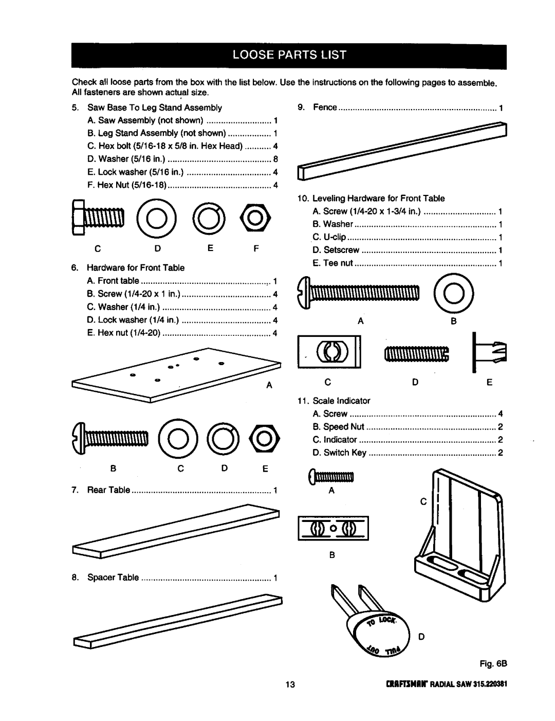
Checkall looseparts from the box with the listbelow. Use the instructionsonthe followingpages to assemble.
Allfasteners are shown actual size.
5. Saw Base To Leg Stand Assembly
A. Saw Assembly (notshown) ........................... 1
B. Leg Stand Assembly (not shown) .................. 1
C. Hex bolt (5/16-18 x 518 in. Hex Head) ........... 4
D. Washer (5/16 in.) ........................................... 8
E. Lock washer (5/16 in.) ................................... 4
F. Hex Nut (6/16-18) ........................................... 4
C D E F
9. Fence.................................................................. 1
6. Hardware for FrontTable
A. Fronttable .................................................... ,.1
B, Screw (1/4-20 x 1 in.) ..................................... 4
C. Washer (1/4 in.) ............................................. 4
D. Lock washer (1/4 in.) ..................................... 4
E. Hex nut (1/4-20) ............................................. 4
11. Scale Indicator
B C D E
7. Rear Table ........................................................... 1
8. SpacerTable ...................................................... 1
10. Leveling Hardware for FrontTable
A. Screw (1/4-20 x 1-3/4 in.) .............................. 1
B.Washer ........................................................... 1
C, U-clip.............................................................. 1
D. Setscrew ........................................................ t
E.Tee nut ........................................................... 1
AB
D E
A. Screw ............................................................. 4
B. Speed Nut ...................................................... 2
C. Indicator ......................................................... 2
D. Switch Key ..................................................... 2
IIoII C
Fig.6B
13 CHR2NH"RADIALSAW316,220381