INSTALLING THE FRONT TABLE
See Figures 23A - 23C.
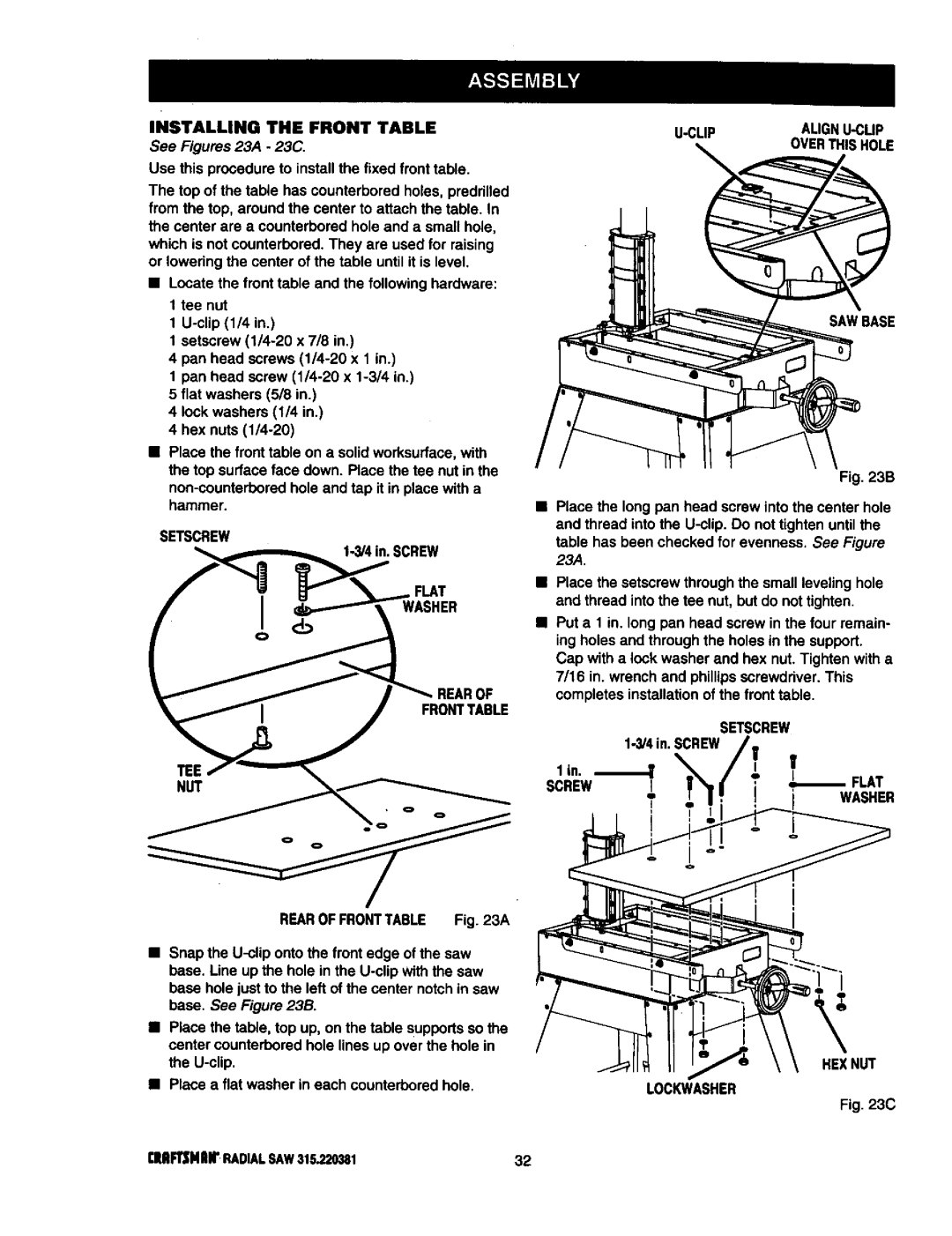
Use this procedure to install the fixed front table.
The top of the table has counterbored holes, predrilled from the top, around the center to attach the table. In the center are a counterbored hole and a small hole,
which is not counterbored. They are used for raising or lowering the center of the table until it is level.
•Locate the front table and the followinghardware: 1 tee nut
1
1 setscrew
4 pan head screws
1 pan head screw
4 lock washers (1/4 in.)
4 hex nuts
•Place the front table on a solid worksurface,with the top surface face down. Race the tee nut in the
SETSCREW |
|
|
|
_ |
|
| SCREW |
f_l |
| _'_._,_ | FLAT |
r | I | _ | WASHER |
| ol | ___ | _k |
|
|
| REAROF |
OVERTHISHOLE
SAWBASE
Fig. 23B
•Place the long pan head screw into the center hole
and thread into the
23A.
•Place the setscrew through the small leveling hole and thread intothe tee nut, but do not tighten.
ing holes and through the holes in the support. Cap with a lock washer and hex nut. Tighten with a
•7/16Put ain1.inwrench. long panand headphillipsscrewscrewdriverin the four. Thisremain- completes installationof the front table.
SCREW L | !'I / | ELAT |
] | _' T' ' | WASHER |
REAROFFRONTTABLE Fig. 23A
•Snap the
•Place the table, top up, on the table supportsso the center counterbored hole lines up over the hole in the
•Place a flat washer in each counterborsd hole.
-i
HEXNUT
LOCKWASHER
Fig. 23C
[lll_NlUr | RADIALSAW315.220381 | 32 |