ALIGNING THE ARM FOR CROSS CUTS
See Figures 29,4 - 2gC,
This procedure checks whether the arm is exscfiy O" for cross cut travel by checking the blade against the table and the miter indicator. Remove the rear table, spacer table, and fence, but leave the front ta_e in place. You will need a framing square, a 3/16 in. hex key, and a pencil,
_k WARNING: Be sure the saw is unplugged before performingthese adjustments. Accidental
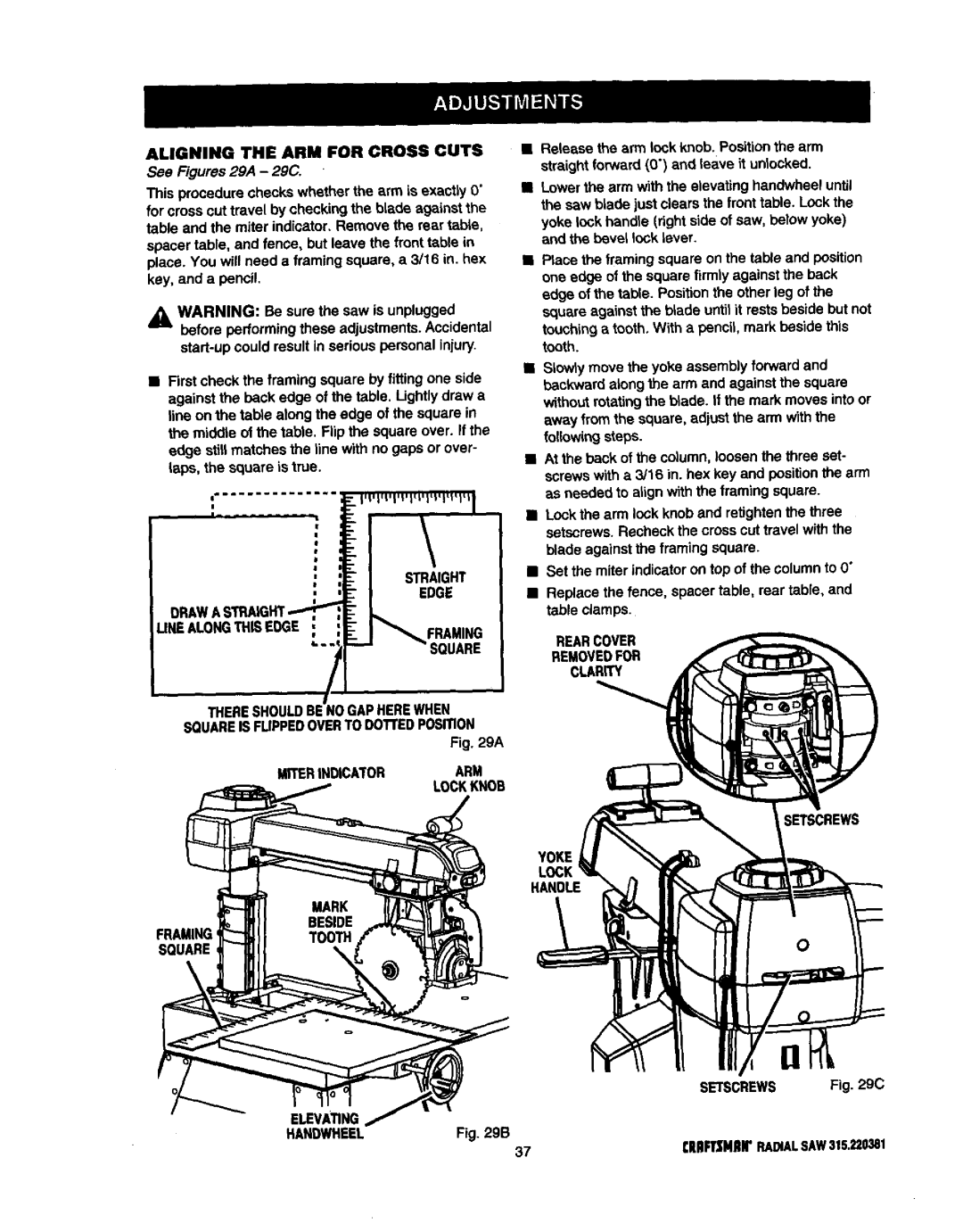
•First check the framing square by fitting one side against the back edge of the table. Lightlydraw a line on the table along the edge of the square in the middle of the table. Flip the square over. If the edge still matches the line with no gaps or over- tape, the square is true.
THERESHOULDBENOGAPHEREWHEN SQUAREIS FUPPEDOVERTODOTrEDPOSITION
Fig. 29A
Release the arm lock knob. Positionthe arm straight forward (0") and leave it unlocked.
Lowerthearm withtheelevatinghandwheeluntil
the saw blade just clears the fronttable. Lock the yoke lock handle (right side of saw, below yoke) and the bevel lock Lever.
•Place the framing square on the table and position one edge of the square firmly against the back edge of the table, Positionthe other leg of the square against the blade until it rests beside but not
touching a tooth. With a pencil, mark beside this tooth.
•Slowlymove the yoke assembly forward and backward along the arm and against the square
without rotatingthe blade. If the mark moves into or away from the square, adjust the arm with the followingsteps.
•At the back of the column, loosen the three set- screws w_tha 3/16 in. hex key and positionthe arm as needed to align with the framing square.
•Lock the arm lock knob and retightenthe three setscrews. Recheck the cross cut travel with the
blade against the framing square.
•Set the miter indicator on top of the column to O"
•Replace the fence, spacer table, rear table, and table clamps.
REARCOVER
REMOVEDFOR
CLARITY
MITERINDICATORARM
LOCKKNOB
Y_E
LOCK
H_O_
FRAMING
SQUARE\
SETSCREWS Fig. 29C
ELEVAnNG
HANDWHEEL | Fig. 29B |
37CRIIFTZNIIrRADIALSAW315.220381