|
|
|
| CY7C1380D, CY7C1382D | ||
|
|
|
| CY7C1380F, CY7C1382F | ||
|
|
|
|
|
|
|
|
|
|
|
| ||
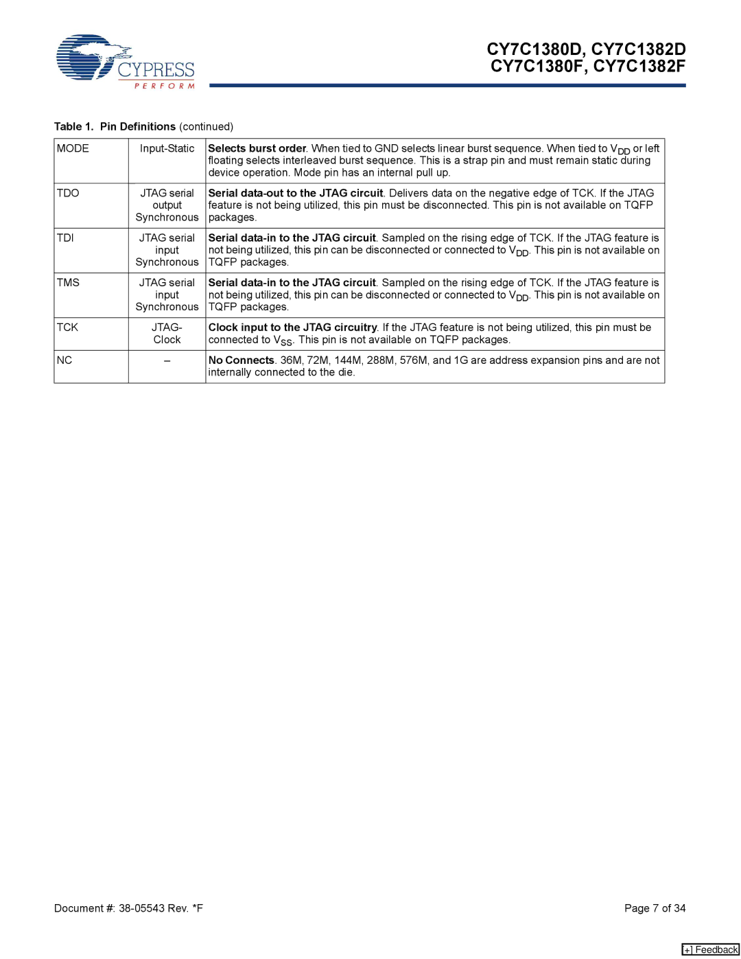
Table 1. Pin Definitions (continued) | ||||||
|
|
|
| |||
MODE | Selects burst order. When tied to GND selects linear burst sequence. When tied to VDD or left |
|
| |||
|
| floating selects interleaved burst sequence. This is a strap pin and must remain static during |
| |||
|
| device operation. Mode pin has an internal pull up. |
| |||
|
|
|
| |||
TDO | JTAG serial | Serial |
|
| ||
| output | feature is not being utilized, this pin must be disconnected. This pin is not available on TQFP |
| |||
| Synchronous | packages. |
| |||
|
|
|
| |||
TDI | JTAG serial | Serial |
|
| ||
| input | not being utilized, this pin can be disconnected or connected to VDD. This pin is not available on |
| |||
| Synchronous | TQFP packages. |
| |||
TMS | JTAG serial | Serial |
|
| ||
| input | not being utilized, this pin can be disconnected or connected to VDD. This pin is not available on |
| |||
| Synchronous | TQFP packages. |
| |||
|
|
|
| |||
TCK | JTAG- | Clock input to the JTAG circuitry. If the JTAG feature is not being utilized, this pin must be |
|
| ||
| Clock | connected to VSS. This pin is not available on TQFP packages. |
| |||
NC | – | No Connects. 36M, 72M, 144M, 288M, 576M, and 1G are address expansion pins and are not |
|
| ||
|
| internally connected to the die. |
| |||
|
|
|
|
|
|
|
Document #: | Page 7 of 34 |
[+] Feedback