|
|
|
|
|
|
|
| CY7C1380C | |
|
|
|
|
|
|
|
| CY7C1382C | |
|
|
|
|
|
|
|
|
| |
|
|
|
|
|
|
|
|
|
|
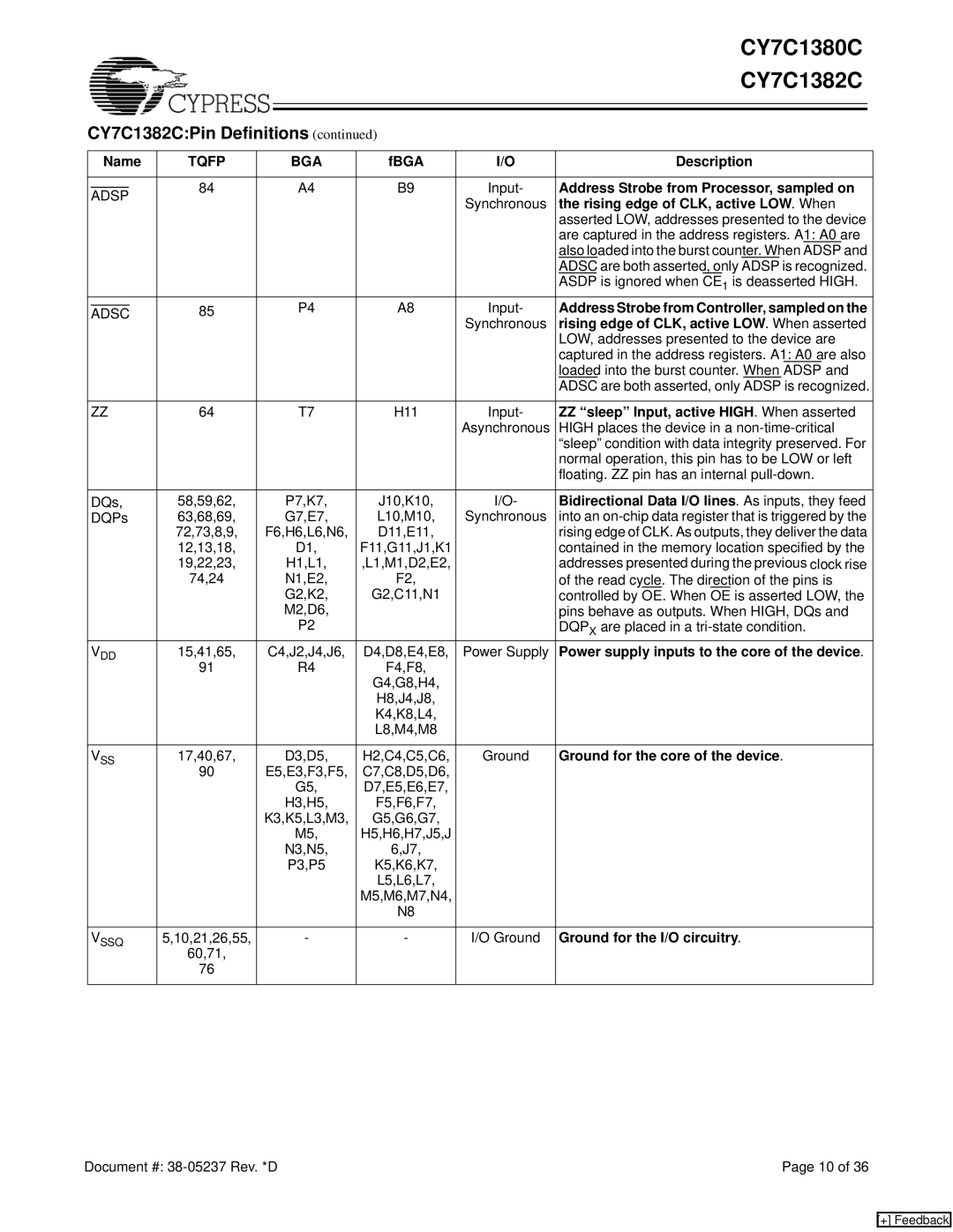
CY7C1382C:Pin Definitions (continued) |
|
|
| ||||||
|
|
|
|
|
|
|
| ||
| Name | TQFP |
| BGA | fBGA | I/O | Description | ||
|
|
|
|
|
|
|
|
| |
|
|
| 84 |
| A4 | B9 | Input- | Address Strobe from Processor, sampled on | |
| ADSP |
| |||||||
|
|
|
|
| Synchronous | the rising edge of CLK, active LOW. When | |||
|
|
|
|
|
|
| |||
|
|
|
|
|
|
|
| asserted LOW, addresses presented to the device | |
|
|
|
|
|
|
|
| are captured in the address registers. A1: A0 are | |
|
|
|
|
|
|
|
| also loaded into the burst counter. When ADSP and | |
|
|
|
|
|
|
|
| ADSC are both asserted, only ADSP is recognized. | |
|
|
|
|
|
|
|
| ASDP is ignored when CE1 is deasserted HIGH. | |
|
|
| 85 |
| P4 | A8 | Input- | Address Strobe from Controller, sampled on the | |
| ADSC |
| |||||||
|
|
|
|
|
|
| Synchronous | rising edge of CLK, active LOW. When asserted | |
|
|
|
|
|
|
|
| LOW, addresses presented to the device are | |
|
|
|
|
|
|
|
| captured in the address registers. A1: A0 are also | |
|
|
|
|
|
|
|
| loaded into the burst counter. When ADSP and | |
|
|
|
|
|
|
|
| ADSC are both asserted, only ADSP is recognized. | |
|
|
|
|
|
|
|
| ||
| ZZ | 64 |
| T7 | H11 | Input- | ZZ “sleep” Input, active HIGH. When asserted | ||
|
|
|
|
|
|
| Asynchronous | HIGH places the device in a | |
|
|
|
|
|
|
|
| “sleep” condition with data integrity preserved. For | |
|
|
|
|
|
|
|
| normal operation, this pin has to be LOW or left | |
|
|
|
|
|
|
|
| floating. ZZ pin has an internal | |
|
|
|
|
|
|
|
| ||
| DQs, | 58,59,62, |
| P7,K7, | J10,K10, | I/O- | Bidirectional Data I/O lines. As inputs, they feed | ||
| DQPs | 63,68,69, |
| G7,E7, | L10,M10, | Synchronous | into an | ||
|
|
| 72,73,8,9, | F6,H6,L6,N6, | D11,E11, |
| rising edge of CLK. As outputs, they deliver the data | ||
|
|
| 12,13,18, |
| D1, | F11,G11,J1,K1 |
| contained in the memory location specified by the | |
|
|
| 19,22,23, |
| H1,L1, | ,L1,M1,D2,E2, |
| addresses presented during the previous clock rise | |
|
|
| 74,24 |
| N1,E2, | F2, |
| of the read cycle. The direction of the pins is | |
|
|
|
|
| G2,K2, | G2,C11,N1 |
| controlled by OE. When OE is asserted LOW, the | |
|
|
|
|
| M2,D6, |
|
| pins behave as outputs. When HIGH, DQs and | |
|
|
|
|
| P2 |
|
| DQPX are placed in a | |
| VDD | 15,41,65, | C4,J2,J4,J6, | D4,D8,E4,E8, | Power Supply | Power supply inputs to the core of the device. | |||
|
|
| 91 |
| R4 | F4,F8, |
|
|
|
|
|
|
|
|
| G4,G8,H4, |
|
|
|
|
|
|
|
|
| H8,J4,J8, |
|
|
|
|
|
|
|
|
| K4,K8,L4, |
|
|
|
|
|
|
|
|
| L8,M4,M8 |
|
|
|
|
|
|
|
|
|
|
| ||
| VSS | 17,40,67, |
| D3,D5, | H2,C4,C5,C6, | Ground | Ground for the core of the device. | ||
|
|
| 90 | E5,E3,F3,F5, | C7,C8,D5,D6, |
|
|
| |
|
|
|
|
| G5, | D7,E5,E6,E7, |
|
|
|
|
|
|
|
| H3,H5, | F5,F6,F7, |
|
|
|
|
|
|
| K3,K5,L3,M3, | G5,G6,G7, |
|
|
| |
|
|
|
|
| M5, | H5,H6,H7,J5,J |
|
|
|
|
|
|
|
| N3,N5, | 6,J7, |
|
|
|
|
|
|
|
| P3,P5 | K5,K6,K7, |
|
|
|
|
|
|
|
|
| L5,L6,L7, |
|
|
|
|
|
|
|
|
| M5,M6,M7,N4, |
|
|
|
|
|
|
|
|
| N8 |
|
|
|
|
|
|
|
|
|
| |||
| VSSQ | 5,10,21,26,55, | - | - | I/O Ground | Ground for the I/O circuitry. | |||
|
|
| 60,71, |
|
|
|
|
|
|
|
|
| 76 |
|
|
|
|
|
|
|
|
|
|
|
|
|
|
|
|
Document #: | Page 10 of 36 |
[+] Feedback