CY7C68013A, CY7C68014A

CY7C68015A, CY7C68016A

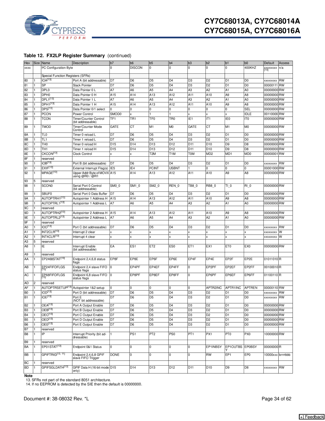
Table 12. FX2LP Register Summary (continued)

Hex

Size

Name

Description

b7

b6

b5

b4

b3

b2

b1

b0

Default

Access

xxxx


I²C Configuration Byte


0

DISCON

0

0

0

0

0

400KHZ

xxxxxxxx

n/a


[14]


Special Function Registers (SFRs)


80

1

IOA[13]

Port A (bit addressable)

D7

D6

D5

D4

D3

D2

D1

D0

xxxxxxxx

RW

81

1

SP

Stack Pointer

D7

D6

D5

D4

D3

D2

D1

D0

00000111

RW

82

1

DPL0

Data Pointer 0 L

A7

A6

A5

A4

A3

A2

A1

A0

00000000

RW

83

1

DPH0

Data Pointer 0 H

A15

A14

A13

A12

A11

A10

A9

A8

00000000

RW

84

1

DPL1[13]

Data Pointer 1 L

A7

A6

A5

A4

A3

A2

A1

A0

00000000

RW

85

1

DPH1[13]

Data Pointer 1 H

A15

A14

A13

A12

A11

A10

A9

A8

00000000

RW

86

1

DPS[13]

Data Pointer 0/1 select

0

0

0

0

0

0

0

SEL

00000000

RW

87

1

PCON

Power Control

SMOD0

x

1

1

x

x

x

IDLE

00110000

RW

88

1

TCON

Timer/Counter Control

TF1

TR1

TF0

TR0

IE1

IT1

IE0

IT0

00000000

RW


(bit addressable)


89

1

TMOD

Timer/Counter Mode

GATE

CT

M1

M0

GATE

CT

M1

M0

00000000

RW


Control


8A

1

TL0

Timer 0 reload L

D7

D6

D5

D4

D3

D2

D1

D0

00000000

RW

8B

1

TL1

Timer 1 reload L

D7

D6

D5

D4

D3

D2

D1

D0

00000000

RW

8C

1

TH0

Timer 0 reload H

D15

D14

D13

D12

D11

D10

D9

D8

00000000

RW

8D

1

TH1

Timer 1 reload H

D15

D14

D13

D12

D11

D10

D9

D8

00000000

RW

8E

1

CKCON[13]

Clock Control

x

x

T2M

T1M

T0M

MD2

MD1

MD0

00000001

RW

8F

1

reserved


90

1

IOB[13]

Port B (bit addressable)

D7

D6

D5

D4

D3

D2

D1

D0

xxxxxxxx

RW

91

1

EXIF[13]

External Interrupt Flag(s)

IE5

IE4

I²CINT

USBNT

1

0

0

0

00001000

RW

92

1

MPAGE[13]

Upper Addr Byte of MOVX

A15

A14

A13

A12

A11

A10

A9

A8

00000000

RW


using @R0 / @R1


93

5

reserved


98

1

SCON0

Serial Port 0 Control

SM0_0

SM1_0

SM2_0

REN_0

TB8_0

RB8_0

TI_0

RI_0

00000000

RW


(bit addressable)


99

1

SBUF0

Serial Port 0 Data Buffer

D7

D6

D5

D4

D3

D2

D1

D0

00000000

RW

9A

1

AUTOPTRH1[13]

Autopointer 1 Address H

A15

A14

A13

A12

A11

A10

A9

A8

00000000

RW

9B

1

AUTOPTRL1[13]

Autopointer 1 Address L

A7

A6

A5

A4

A3

A2

A1

A0

00000000

RW

9C

1

reserved


9D

1

AUTOPTRH2[13]

Autopointer 2 Address H

A15

A14

A13

A12

A11

A10

A9

A8

00000000

RW

9E

1

AUTOPTRL2[13]

Autopointer 2 Address L

A7

A6

A5

A4

A3

A2

A1

A0

00000000

RW

9F

1

reserved


A0

1

IOC[13]

Port C (bit addressable)

D7

D6

D5

D4

D3

D2

D1

D0

xxxxxxxx

RW

A1

1

INT2CLR[13]

Interrupt 2 clear

x

x

x

x

x

x

x

x

xxxxxxxx

W

A2

1

INT4CLR[13]

Interrupt 4 clear

x

x

x

x

x

x

x

x

xxxxxxxx

W

A3

5

reserved


A8

1

IE

Interrupt Enable

EA

ES1

ET2

ES0

ET1

EX1

ET0

EX0

00000000

RW


(bit addressable)


A9

1

reserved


AA

1

EP2468STAT[13]

Endpoint 2,4,6,8 status

EP8F

EP8E

EP6F

EP6E

EP4F

EP4E

EP2F

EP2E

01011010

R


flags


AB

1

EP24FIFOFLGS

Endpoint 2,4 slave FIFO

0

EP4PF

EP4EF

EP4FF

0

EP2PF

EP2EF

EP2FF

00100010

R


[13]

status flags


AC

1

EP68FIFOFLGS

Endpoint 6,8 slave FIFO

0

EP8PF

EP8EF

EP8FF

0

EP6PF

EP6EF

EP6FF

01100110

R


[13]

status flags


AD

2

reserved


AF

1

AUTOPTRSETUP[13]

Autopointer 1&2 setup

0

0

0

0

0

APTR2INC

APTR1INC

APTREN

00000110

RW

B0

1

IOD[13]

Port D (bit addressable)

D7

D6

D5

D4

D3

D2

D1

D0

xxxxxxxx

RW

B1

1

IOE[13]

Port E

D7

D6

D5

D4

D3

D2

D1

D0

xxxxxxxx

RW


(NOT bit addressable)


B2

1

OEA[13]

Port A Output Enable

D7

D6

D5

D4

D3

D2

D1

D0

00000000

RW

B3

1

OEB[13]

Port B Output Enable

D7

D6

D5

D4

D3

D2

D1

D0

00000000

RW

B4

1

OEC[13]

Port C Output Enable

D7

D6

D5

D4

D3

D2

D1

D0

00000000

RW

B5

1

OED[13]

Port D Output Enable

D7

D6

D5

D4

D3

D2

D1

D0

00000000

RW

B6

1

OEE[13]

Port E Output Enable

D7

D6

D5

D4

D3

D2

D1

D0

00000000

RW

B7

1

reserved


B8

1

IP

Interrupt Priority (bit ad-

1

PS1

PT2

PS0

PT1

PX1

PT0

PX0

10000000

RW


dressable)


B9

1

reserved


BA

1

EP01STAT[13]

Endpoint 0&1 Status

0

0

0

0

0

EP1INBSY

EP1OUTBS

EP0BSY

00000000

R


Y


BB

1

GPIFTRIG[13, 11]

Endpoint 2,4,6,8 GPIF

DONE

0

0

0

0

RW

EP1

EP0

10000xxx

brrrrbbb


slave FIFO Trigger


BC

1

reserved


BD

1

GPIFSGLDATH[13]

GPIF Data H (16-bit mode

D15

D14

D13

D12

D11

D10

D9

D8

xxxxxxxx

RW


only)


Note

13.SFRs not part of the standard 8051 architecture.

14.If no EEPROM is detected by the SIE then the default is 00000000.

Document #: 38-08032 Rev. *L

Page 34 of 62

[+] Feedback

Page 34
Image 34
Cypress CY7C68013A manual DPL0

CY7C68013A specifications

The Cypress CY7C68013A is a high-performance USB microcontroller that belongs to Cypress's FX2LP family, specifically designed for USB applications. This microcontroller is well-regarded for its versatility, making it a popular choice for developers engaged in USB-enabled projects.

One of the main features of the CY7C68013A is its ability to support USB 2.0, with both high-speed (480 Mbps) and full-speed (12 Mbps) operation. This capability allows developers to take full advantage of the USB interface for data transfer, making it suitable for applications that require fast and efficient data communication. The device integrates a USB controller along with an 8051-compatible microcontroller, providing a seamless interface for USB transactions while also allowing for custom processing tasks.

The CY7C68013A offers 32 KB of internal RAM, which is a valuable resource for data buffering and temporary storage during data transfer operations. Additionally, it includes a programmable 8-bit I/O interface, which can be tailored to various application needs, facilitating control over peripheral devices. The microcontroller also features a 16-bit address bus and a 16-bit data bus, enhancing its ability to interface with external memory and components.

In terms of development, moving from concept to production becomes easier due to the availability of development kits and software support. The CY7C68013A is compatible with Cypress's EZ-USB development environment, which includes APIs and libraries that simplify the coding process. This software support empowers developers to create sophisticated USB-related applications without needing extensive background knowledge in USB protocol intricacies.

Regarding power efficiency, the CY7C68013A operates at low power consumption levels, making it suitable for battery-operated devices. It supports various low-power modes, which further enhances its appeal for portable applications.

Overall, the Cypress CY7C68013A stands out for its robust features, flexibility, and ease of use, making it an ideal choice for engineers working on USB-centric designs. Its combination of high-speed USB functionality, ample internal resources, and strong software support positions it as a go-to microcontroller for a wide variety of applications, ranging from consumer electronics to industrial systems.