CY8C22x13 Final Data Sheet | PSoC™ Overview |
|
|
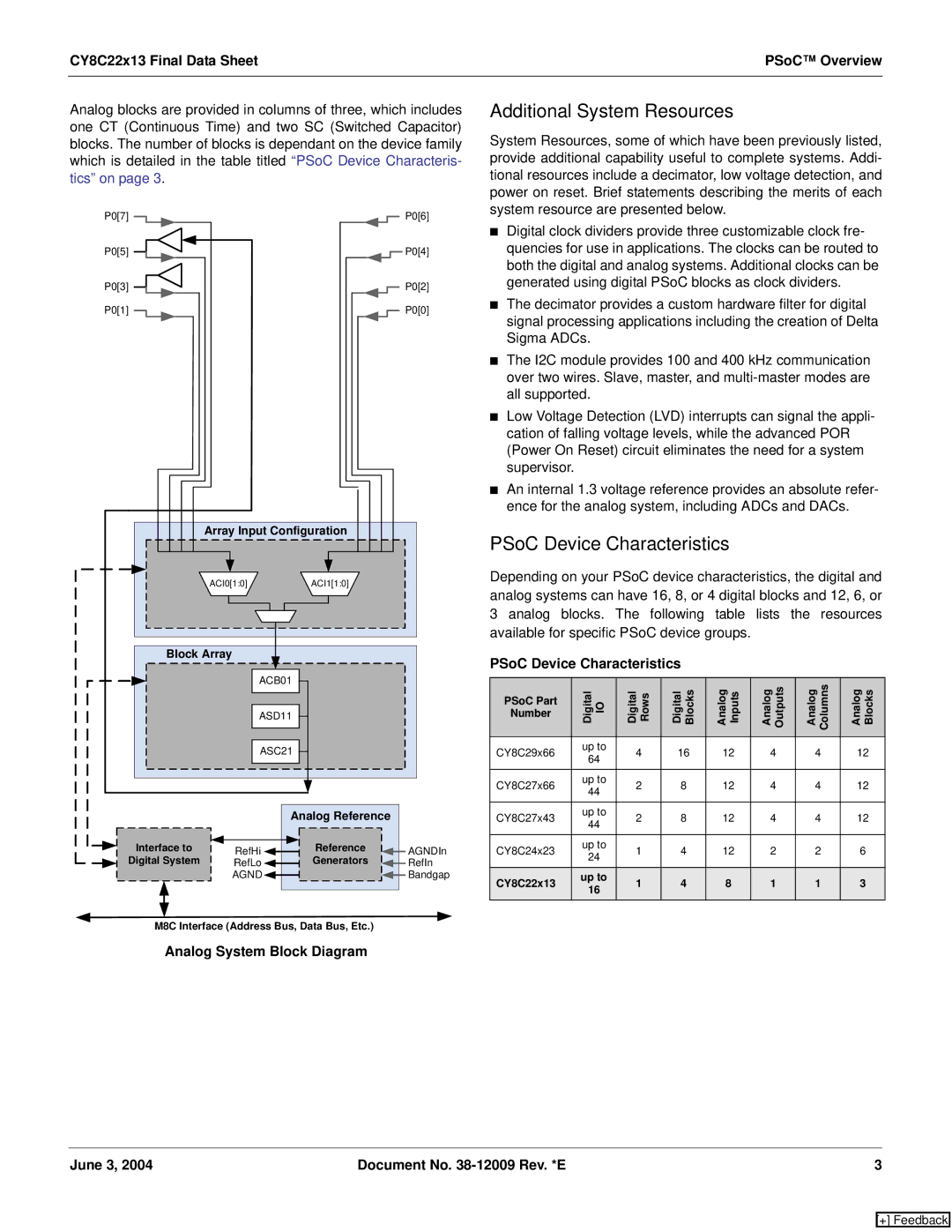
Analog blocks are provided in columns of three, which includes one CT (Continuous Time) and two SC (Switched Capacitor) blocks. The number of blocks is dependant on the device family which is detailed in the table titled “PSoC Device Characteris- tics” on page 3.
P0[7] |
|
|
|
|
|
|
|
|
|
|
|
|
|
|
|
|
|
|
|
|
|
|
| P0[6] |
P0[5] |
|
|
|
|
|
|
|
|
|
|
|
|
|
|
|
| P0[4] | |||||||
P0[3] |
|
|
|
|
|
|
|
|
|
|
|
|
|
|
| P0[2] | ||||||||
P0[1] |
|
|
|
|
|
|
|
|
|
|
|
|
|
|
|
|
|
|
|
|
|
|
| P0[0] |
|
|
|
|
|
|
|
|
|
|
|
|
|
|
|
|
|
|
|
|
|
|
|
|
|
|
|
|
|
|
|
|
|
|
|
|
|
|
|
|
|
|
|
|
|
|
|
|
|
|
|
|
|
|
|
|
|
|
|
|
|
|
|
|
|
|
|
|
|
|
|
|
|
|
|
Array Input Configuration | |
ACI0[1:0] | ACI1[1:0] |
Block Array |
|
| ACB01 |
| ASD11 |
| ASC21 |
Analog Reference
Interface to | RefHi | Reference | AGNDIn | |
Digital System | Generators | |||
RefLo | RefIn | |||
| AGND |
| Bandgap |
M8C Interface (Address Bus, Data Bus, Etc.)
Analog System Block Diagram
Additional System Resources
System Resources, some of which have been previously listed, provide additional capability useful to complete systems. Addi- tional resources include a decimator, low voltage detection, and power on reset. Brief statements describing the merits of each system resource are presented below.
■Digital clock dividers provide three customizable clock fre- quencies for use in applications. The clocks can be routed to both the digital and analog systems. Additional clocks can be generated using digital PSoC blocks as clock dividers.
■The decimator provides a custom hardware filter for digital signal processing applications including the creation of Delta Sigma ADCs.
■The I2C module provides 100 and 400 kHz communication over two wires. Slave, master, and
■Low Voltage Detection (LVD) interrupts can signal the appli- cation of falling voltage levels, while the advanced POR (Power On Reset) circuit eliminates the need for a system supervisor.
■An internal 1.3 voltage reference provides an absolute refer- ence for the analog system, including ADCs and DACs.
PSoC Device Characteristics
Depending on your PSoC device characteristics, the digital and analog systems can have 16, 8, or 4 digital blocks and 12, 6, or 3 analog blocks. The following table lists the resources available for specific PSoC device groups.
PSoC Device Characteristics
PSoC Part | Digital IO | Digital Rows | Digital Blocks | Analog Inputs | Analog Outputs | Analog Columns | Analog Blocks | |
Number |
|
|
|
|
|
|
| |
|
|
|
|
|
|
|
| |
CY8C29x66 | up to | 4 | 16 | 12 | 4 | 4 | 12 | |
64 | ||||||||
|
|
|
|
|
|
| ||
|
|
|
|
|
|
|
| |
CY8C27x66 | up to | 2 | 8 | 12 | 4 | 4 | 12 | |
44 | ||||||||
|
|
|
|
|
|
| ||
|
|
|
|
|
|
|
| |
CY8C27x43 | up to | 2 | 8 | 12 | 4 | 4 | 12 | |
44 | ||||||||
|
|
|
|
|
|
| ||
|
|
|
|
|
|
|
| |
CY8C24x23 | up to | 1 | 4 | 12 | 2 | 2 | 6 | |
24 | ||||||||
|
|
|
|
|
|
| ||
|
|
|
|
|
|
|
| |
CY8C22x13 | up to | 1 | 4 | 8 | 1 | 1 | 3 | |
16 | ||||||||
|
|
|
|
|
|
| ||
|
|
|
|
|
|
|
|
June 3, 2004 | Document No. | 3 |
[+] Feedback