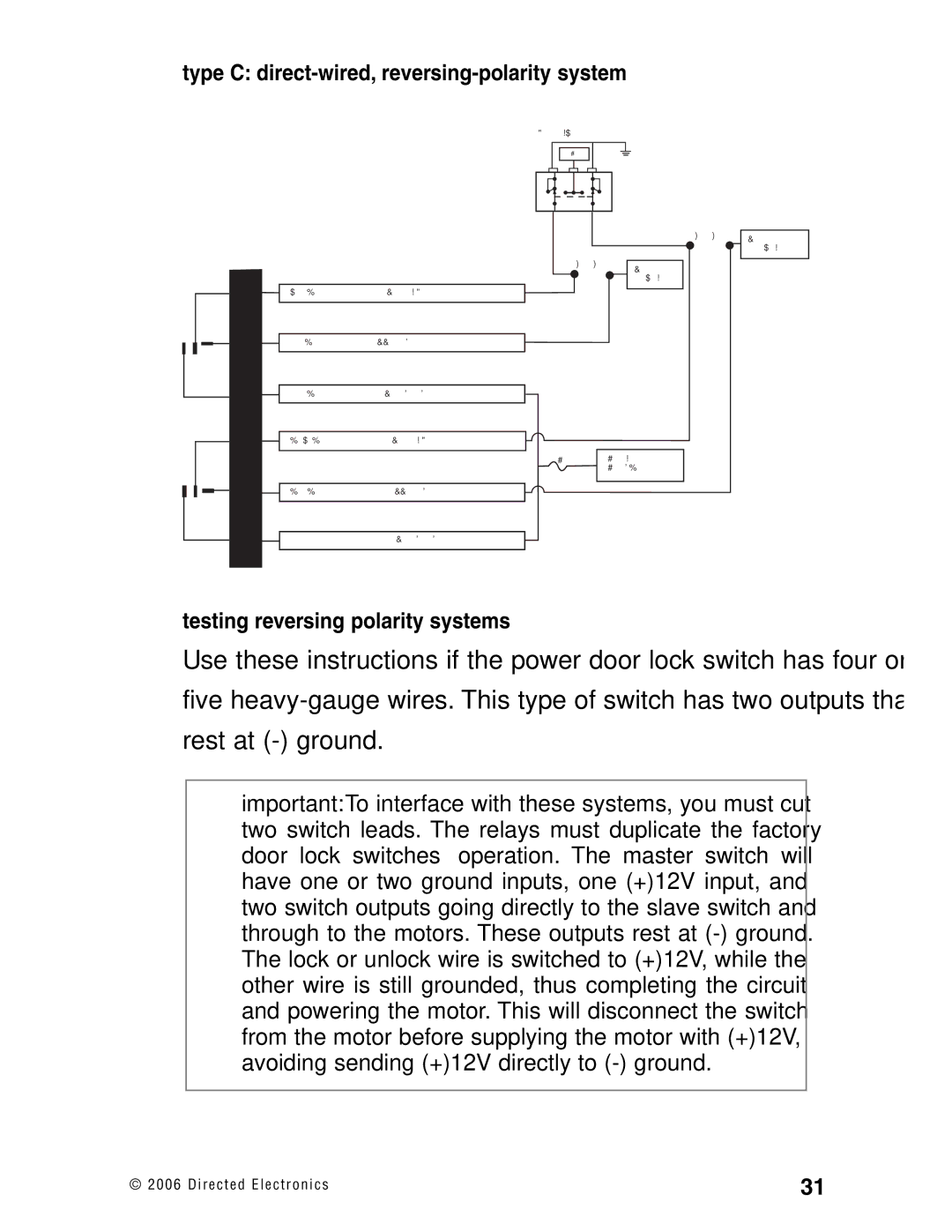
type C: direct-wired, reversing-polarity system
DOOR LOCK SWITCH
H2/2
LOCK #87 #30A H2/3
RELAY
#87A
H2/4
LOCK
WHITE/BLACK | LOCK #87A NORMALLY CLOSED |
|
|
|
|
GREEN/BLACK | LOCK #30 COMMON (OUTPUT) |
|
|
|
|
VIOLET/BLACK | LOCK #87 NORMALLY OPEN (INPUT) |
|
|
(+) 12V
UNLOCK
X CUT X | MOTOR |
| UNLOCK WIRES |
X CUT X | MOTOR |
| |
| LOCK WIRES |
#87 #30A
UNLOCK
RELAY #87A
H2/5 | BROWN/BLACK | UNLOCK #87A NORMALLY CLOSED |
| |
|
|
|
| 15A |
H2/6 |
|
|
| |
BLUE/BLACK | UNLOCK #30 COMMON (OUTPUT) |
| ||
H2/7 |
|
|
|
|
|
|
| ||
| VIOLET | UNLOCK #87 NORMALLY OPEN (INPUT) |
| |
|
| |||
|
|
|
|
|
+12V CONSTANT
(15A CAPABLE)
testing reversing polarity systems
Use these instructions if the power door lock switch has four or five
important: To interface with these systems, you must cut two switch leads. The relays must duplicate the factory door lock switches’ operation. The master switch will have one or two ground inputs, one (+)12V input, and two switch outputs going directly to the slave switch and through to the motors. These outputs rest at
© 2 0 0 6 D i r e c t e d E l e c t r o n i c s | 31 |
