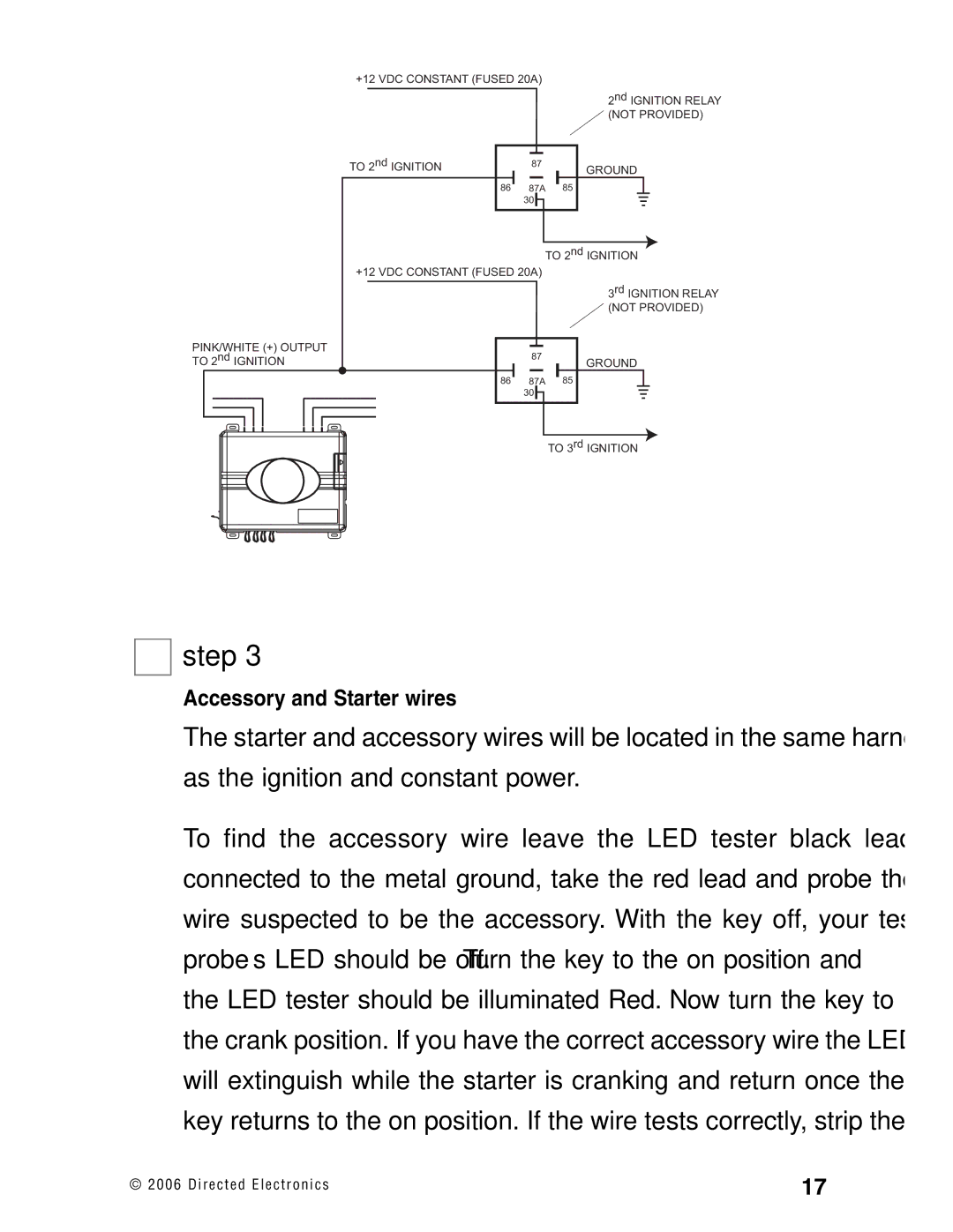
+12 VDC CONSTANT (FUSED 20A)
|
|
|
|
|
| 2nd IGNITION RELAY |
|
|
|
|
|
| (NOT PROVIDED) |
|
|
|
|
|
|
|
TO 2nd IGNITION |
|
|
|
|
| |
87 |
|
| GROUND | |||
|
|
| 85 | |||
86 | 87A |
| ||||
30 ![]()
TO 2nd IGNITION
+12 VDC CONSTANT (FUSED 20A)
3rd IGNITION RELAY ![]() (NOT PROVIDED)
(NOT PROVIDED)
PINK/WHITE (+) OUTPUT | 87 |
| |
TO 2nd IGNITION | GROUND | ||
| |||
86 | 87A | 85 | |
| 30 |
| |
|
| TO 3rd IGNITION |
➜
step 3
Accessory and Starter wires
The starter and accessory wires will be located in the same harness as the ignition and constant power.
To find the accessory wire leave the LED tester black lead connected to the metal ground, take the red lead and probe the wire suspected to be the accessory. With the key off, your test probe’s LED should be off. Turn the key to the on position and the LED tester should be illuminated Red. Now turn the key to the crank position. If you have the correct accessory wire the LED will extinguish while the starter is cranking and return once the key returns to the on position. If the wire tests correctly, strip the
© 2 0 0 6 D i r e c t e d E l e c t r o n i c s | 17 |