Departmental Switch Model DS-16B
Hardware Reference Manual
Copyright 2000 EMC Corporation. All rights reserved
Departmental Switch Model DS-16B Hardware Reference Manual
Trademark Information
FCC Warning USA only
Departmental Switch Model DS-16B Hardware Reference Manual
Contents
Chapter Switch Management
Chapter Front Panel Diagnostics
Appendix a Specifications
Appendix B Switch Support
Appendix C Error Messages
Departmental Switch Model DS-16B Hardware Reference Manual
Figures
Figures
Preface
Related Publications Conventions Used in This Manual
For Information On See
Command line arguments when used in text
Examples of specific command entries that you
Arguments used in examples of command line
Ask for Customer Service
Departmental Switch Model DS-16B Hardware Reference Manual
Introduction
Introduction System Components
DS-16B Switch
Features
Following features
Introduction
Performance
Manageability
Unit may be managed in band or out of band via Telnet, via
Ethernet port
System Components
Fabric Operating
System
GBICs
Installation
Unpacking the Switch
Power Requirements
Site Considerations
Cooling
Requirements
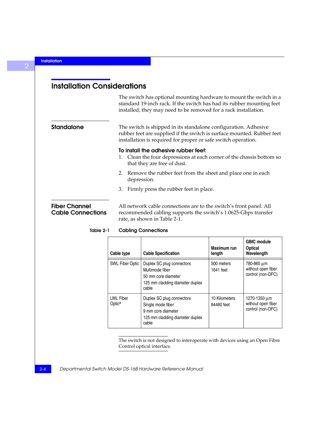
Installation Considerations
To install the adhesive rubber feet
Standalone
Fiber Channel
Verify Power-On Self
Ethernet
Connection
Test Post
Departmental Switch Model DS-16B Hardware Reference Manual
Switch Management
Comparing Switch Management Access Methods
SES
Managing Through Front Panel Buttons
Control Buttons
Select Menu Configuration Menu
Activating Menu
Display
Front panel buttons activates the display
DS-16B Switch Menus
Following menus are controlled using the front panel buttons
Commands
Shows the front panel commands and their equivalent
Telnet command
Menu Front Panel Telnet Command Default
Unset QuickLoop Port Configure QuickLoop Partner WWN
Cmem Data Retention Test
Configuration Menu
Configuration menu See
Ratov Edtov
Configuration menu
Ethernet IP address 10
To enter an IP address
Ethernet Subnetmask none
To update the Fibre Channel’s IP address
Fibre Channel IP Address
Fibre Channel IP address
Fibre Channel Subnetmask
Gateway address
To enter the gateway address
Domain
BBcredit
Ratov Pressing Enter while Ratov is selected, displays
Ratov
Edtov Pressing Enter while Edtov is selected, displays
Edtov
Operating Mode
Operating modes for the switch are
For the corresponding operating mode
Operating modes are determined by the host adapter. The six
VC Link Ctl
VC Class 2
VC Class 3
VC Multicast
Reset to Default Accept? Yes No
VC Priorities 0,1,2,2,2,2,3,3
Frame Collection Method? Bundle/Piling
Default values
Allows you to select commands
Operation Menu
Menu. Pressing Enter while the Operation Menu is selected
Switch Online
Operation Menu Switch Offline
Operation Menu Switch Online
Operation Menu Port Disable
Operation Menu Port Enable
Port Enable Accept? Yes No
Operation Menu Reboot
Reboot Accept? Yes No
Switch Name sw15
Status Menu
Menu is informational only you cannot make changes to
Status Menu See
Booted At Sat Sep 19 183420
Worldwide Name 1000606900e
Firmware Version
Current Date Mon Oct 21 102335
Boot Prom Date Jun 12 084829 PST
Powered Time 137 days
Flash Date Jun 12 084829 PST
Up Time Day
Module TypeL
Port Throughput 75MB/s
Temperature 36 34 37 36
3Temperature Sensor Approximate Locations on Motherboard
Error Log Selecting Error Log, then pressing Enter, displays
Feb 12 084829 Err SENSOR-FAILED-3
Test Menu
Licenses
Licenses 01f
Front Panel Diagnostics
Front Panel Diagnostics
Diagnostic
This section gives a diagnostic overview and discusses
Overview
Diagnostic Front
Fault
Removing Power
Panel Displays
Status and Activity Indicators
Indicators
Front Panel LED Port
Color and flash speed of each port’s LED, as described
Power-On
Diagnostics Post
Diagnostic Tests
Switch Offline Accept? Yes No
Switch Online Accept? Yes No
System Memory Test at 0x1021d460 len
Offline Tests Offline & Online Tests
Related error messages DIAG-MEMORY, DIAG-MEMSZ
Related error messages DIAG-REGERR, DIAG-REGERRUNRST
If the memory tests OK, the front panel displays
0x10199a10 len 13091456 ramTest passed
Related error messages DIAG-CMBISTRO, DIAG-CMBISRF
Central MemTest passed
Related error messages DIAG-INIT, DIAG-PORTDIED
Port Loopback Test Aborted
SpinSilk Press any button to terminate
Push Button Test To exit
Specifications
General Specifications
Table A-1 shows the switch specifications
Specifications Description
Fabric Management Specifications
Table A-2 shows Fabric management specifications
Safety Specifications
Table A-3 Shows Safety specifications
Safety
Specifications
Switch’s primary operating environments are server rooms
Specification Value
Optical Port
Power Supply
Dimensions
Rack Mount Dimensions
Table Top Dimensions
Switch Support
Switch Support
Support Tool
Error Messages
Error Message Formats
Front Panel
Message Formats
Feb 12
To display error message from the front panel
Diagnostic Error Message Formats
Failed test Replace
Error Message
Error Number Test Name Error Name
Numbers
DIAG-TIMEOUT
DIAG-CMBISRTO
DIAG-CMBISRF
DIAG-LCMEMTX
DIAG-ERRSTAT Encin
DIAG-ERRSTAT CRC
DIAG-ERRSTAT Trunc
DIAG-ERRSTAT 2LONG
DIAG-ERRSTATENCIN
DIAG-ERRSTATCRL
DIAG-ERRSTATTRUNC
DIAG-ERRSTAT2LONG
DIAG-PORTSTOPPED
Error Message Tables
Message Description Probable Cause Action
CMI message received failed bad
DIAG-ERRSTAT
Asic failure Replace Err#1F26
Message Description Probable Cause
FLASH, Badmirror
RPC, Svcexit
RPC, Svcreg
FCIU, IUBAD, L, S
FCIU, IUCOUNT, L, S
FCPH, EXCHBAD, L, S
FCPH, EXCHFREE, L, S
MQ, QWRITE, L, M
SYS BADPTR, Logerror
SYS FLASHRD, Logerror
SYS FLASHWR, Logerror
TIMERS, MSG,LOGWARNING
Logerror
MCAST, Noparentlsr
UCAST, RRTIM, Logcritical
Sales and Service Locations
International Sales
Locations
Departmental Switch Model DS-16B Hardware Reference Manual
Departmental Switch Model DS-16B Hardware Reference Manual
Index
Index
Departmental Switch Model DS-16B Hardware Reference Manual
Departmental Switch Model DS-16B Hardware Reference Manual