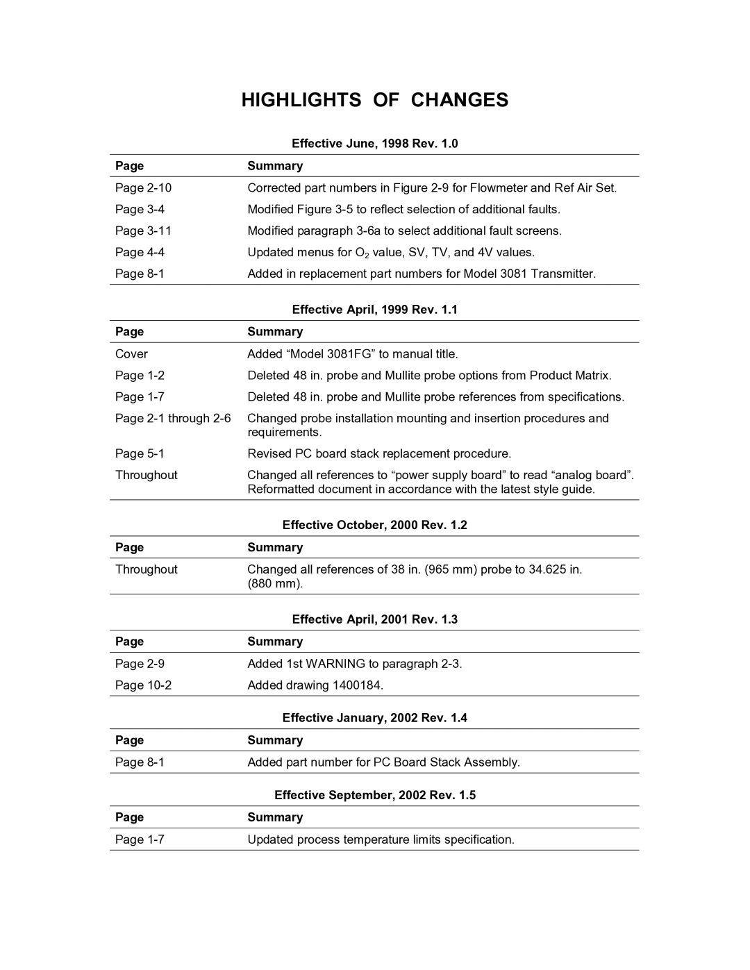
| HIGHLIGHTS OF CHANGES |
| Effective June, 1998 Rev. 1.0 |
|
|
Page | Summary |
|
|
Page | Corrected part numbers in Figure |
Page | Modified Figure |
Page | Modified paragraph |
Page | Updated menus for O2 value, SV, TV, and 4V values. |
Page | Added in replacement part numbers for Model 3081 Transmitter. |
|
|
| Effective April, 1999 Rev. 1.1 |
|
|
Page | Summary |
|
|
Cover | Added “Model 3081FG” to manual title. |
Page | Deleted 48 in. probe and Mullite probe options from Product Matrix. |
Page | Deleted 48 in. probe and Mullite probe references from specifications. |
Page
| requirements. |
Page | Revised PC board stack replacement procedure. |
Throughout | Changed all references to “power supply board” to read “analog board”. |
| Reformatted document in accordance with the latest style guide. |
| Effective October, 2000 Rev. 1.2 |
|
|
Page | Summary |
|
|
Throughout | Changed all references of 38 in. (965 mm) probe to 34.625 in. |
| (880 mm). |
|
|
| Effective April, 2001 Rev. 1.3 |
|
|
Page | Summary |
|
|
Page | Added 1st WARNING to paragraph |
Page | Added drawing 1400184. |
|
|
| Effective January, 2002 Rev. 1.4 |
|
|
Page | Summary |
|
|
Page | Added part number for PC Board Stack Assembly. |
|
|
| Effective September, 2002 Rev. 1.5 |
|
|
Page | Summary |
|
|
Page | Updated process temperature limits specification. |
|
|
