Instruction Manual
Model 3081FG
pairs are recommended. Ground the trans- mitter housing to an earth ground to prevent unwanted electromagnetic interference (EMI) or radio frequency interference (RFI).
NOTE
For optimum EMI/RFI immunity, shield the
NOTE
Never run signal or sensor wiring in the same conduit, or open tray, with power cables. Keep signal or sensor wiring at least 12 in. (0.3 m) away from other electrical equipment and 6.5 ft (2 m) from heavy electrical equipment.
It is necessary to prevent moisture from entering the Model 3081 Transmitter hous- ing. The use of
Moisture accumulation in the transmit- ter housing can affect its performance and may void its warranty.
b.Oxygen Probe Signal Connections
1.Two signals represent the O2 value and the cell temperature. The probe pro- vides these values to the Model 3081 Transmitter for processing and signal conditioning.
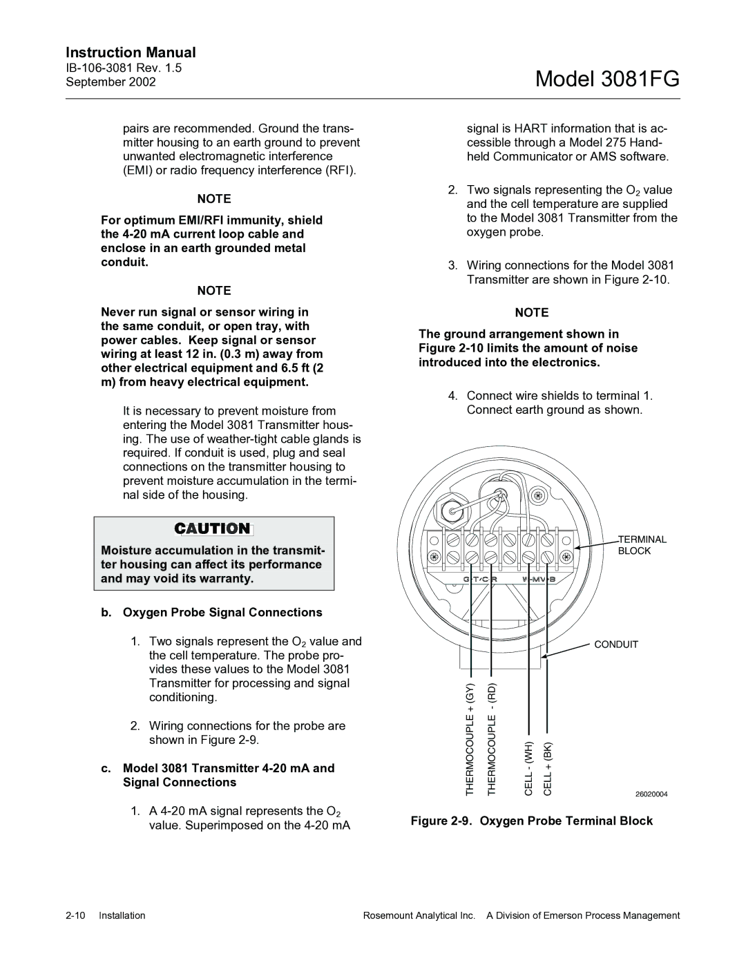
2.Wiring connections for the probe are shown in Figure
c.Model 3081 Transmitter 4-20 mA and Signal Connections
1.A
signal is HART information that is ac- cessible through a Model 275 Hand- held Communicator or AMS software.
2.Two signals representing the O2 value and the cell temperature are supplied to the Model 3081 Transmitter from the oxygen probe.
3.Wiring connections for the Model 3081 Transmitter are shown in Figure
NOTE
The ground arrangement shown in Figure
4.Connect wire shields to terminal 1. Connect earth ground as shown.
TERMINAL
BLOCK
|
|
|
|
|
|
| CONDUIT |
|
|
|
|
|
|
|
|
|
|
|
|
|
|
|
|
+(GY) |
|
|
|
| |||
THERMOCOUPLE | THERMOCOUPLE |
|
|
|
| ||
| CELL+(BK) | ||||||
|
|
|
|
|
| 26020004 | |
Figure 2-9. Oxygen Probe Terminal Block
Rosemount Analytical Inc. A Division of Emerson Process Management |