Instruction Manual
Model 3081FG
%
%
26020024
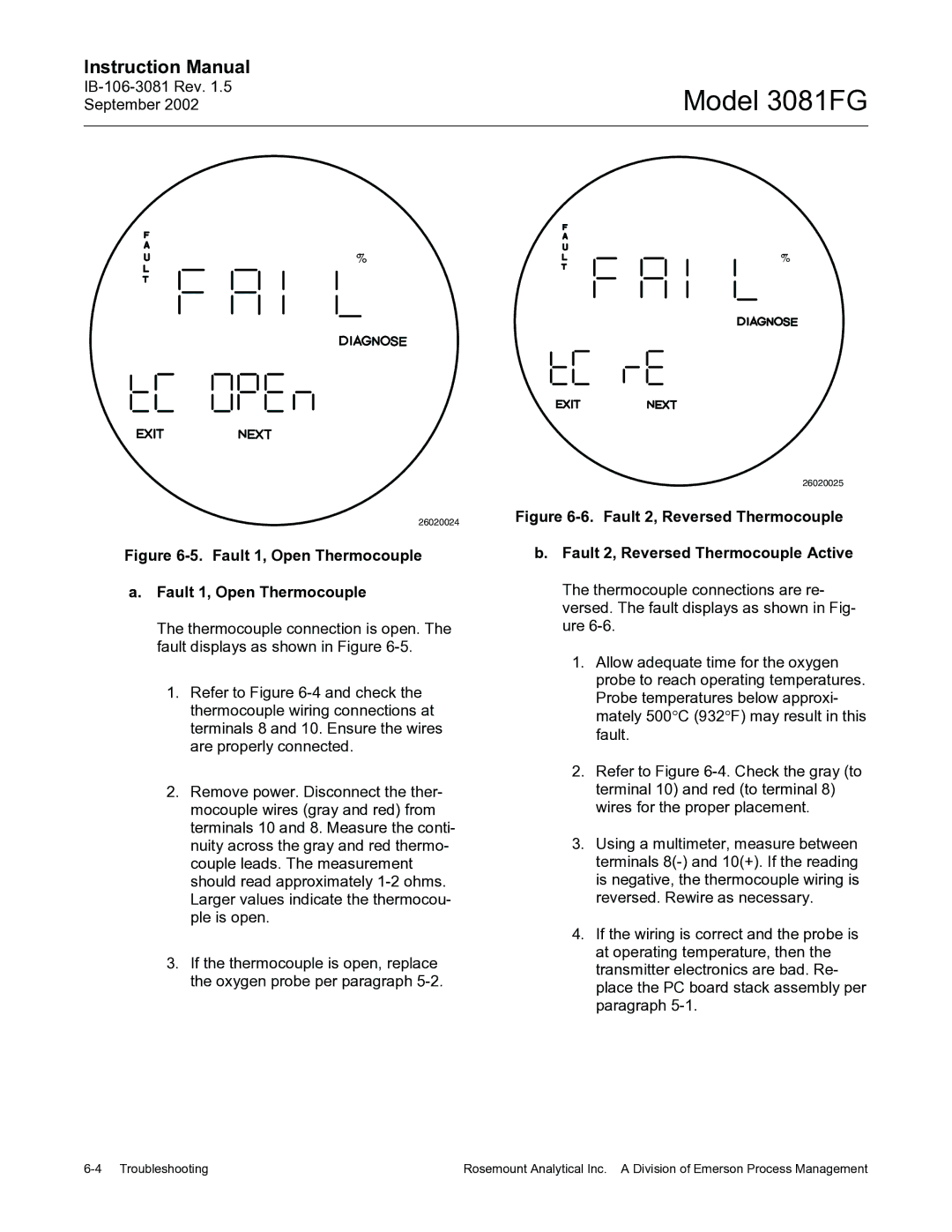
Figure 6-5. Fault 1, Open Thermocouple
a.Fault 1, Open Thermocouple
The thermocouple connection is open. The fault displays as shown in Figure
1.Refer to Figure
2.Remove power. Disconnect the ther- mocouple wires (gray and red) from terminals 10 and 8. Measure the conti- nuity across the gray and red thermo- couple leads. The measurement should read approximately
3.If the thermocouple is open, replace the oxygen probe per paragraph
26020025
Figure 6-6. Fault 2, Reversed Thermocouple
b.Fault 2, Reversed Thermocouple Active
The thermocouple connections are re- versed. The fault displays as shown in Fig- ure
1.Allow adequate time for the oxygen probe to reach operating temperatures. Probe temperatures below approxi- mately 500°C (932°F) may result in this fault.
2.Refer to Figure
3.Using a multimeter, measure between terminals
4.If the wiring is correct and the probe is at operating temperature, then the transmitter electronics are bad. Re- place the PC board stack assembly per paragraph
Rosemount Analytical Inc. A Division of Emerson Process Management |
