Rosemount 5300/5400 Series
Manual Supplement
Verify Alarm Output
Use status information to evaluate measurement validity
Use Heartbeat to detect errors
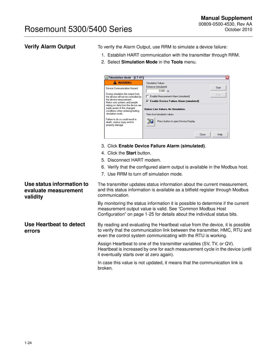
To verify the Alarm Output, use RRM to simulate a device failure:
1.Establish HART communication with the transmitter through RRM.
2.Select Simulation Mode in the Tools menu.
3.Click Enable Device Failure Alarm (simulated).
4.Click the Start button.
5.Disconnect HART modem.
6.Verify that the configured alarm output is available in the Modbus host.
7.Use RRM to turn off simulation mode.
The transmitter updates status information about the current measurement, and this status information is available as a bitfield register through Modbus communication.
By monitoring the status information it is possible to determine if the current measurement output value is valid. See “Common Modbus Host Configuration” on page
By reading and evaluating the Heartbeat value from the device, it is possible to verify that the communication link between the transmitter, HMC, RTU and even the control system communicating with the RTU is working.
Assign Heartbeat to one of the transmitter variables (SV, TV, or QV). Heartbeat is increased by one for each measurement cycle in the device (until it eventually starts over at zero again).
In case this value is not updated, it means that the communication link is broken.