Manual Supplement
Rosemount 5300/5400 Series
INTRODUCTION | The Rosemount 5300 Series and Rosemount 5400 Series transmitters are |
| Modbus compatible measurement devices that support communication with a |
| Remote Terminal Unit (RTU) using a subset of read, write, and diagnostic |
| commands used by most Modbus compatible host controllers. The |
| transmitters also support communication through Levelmaster and Modbus |
| ASCII protocols. |
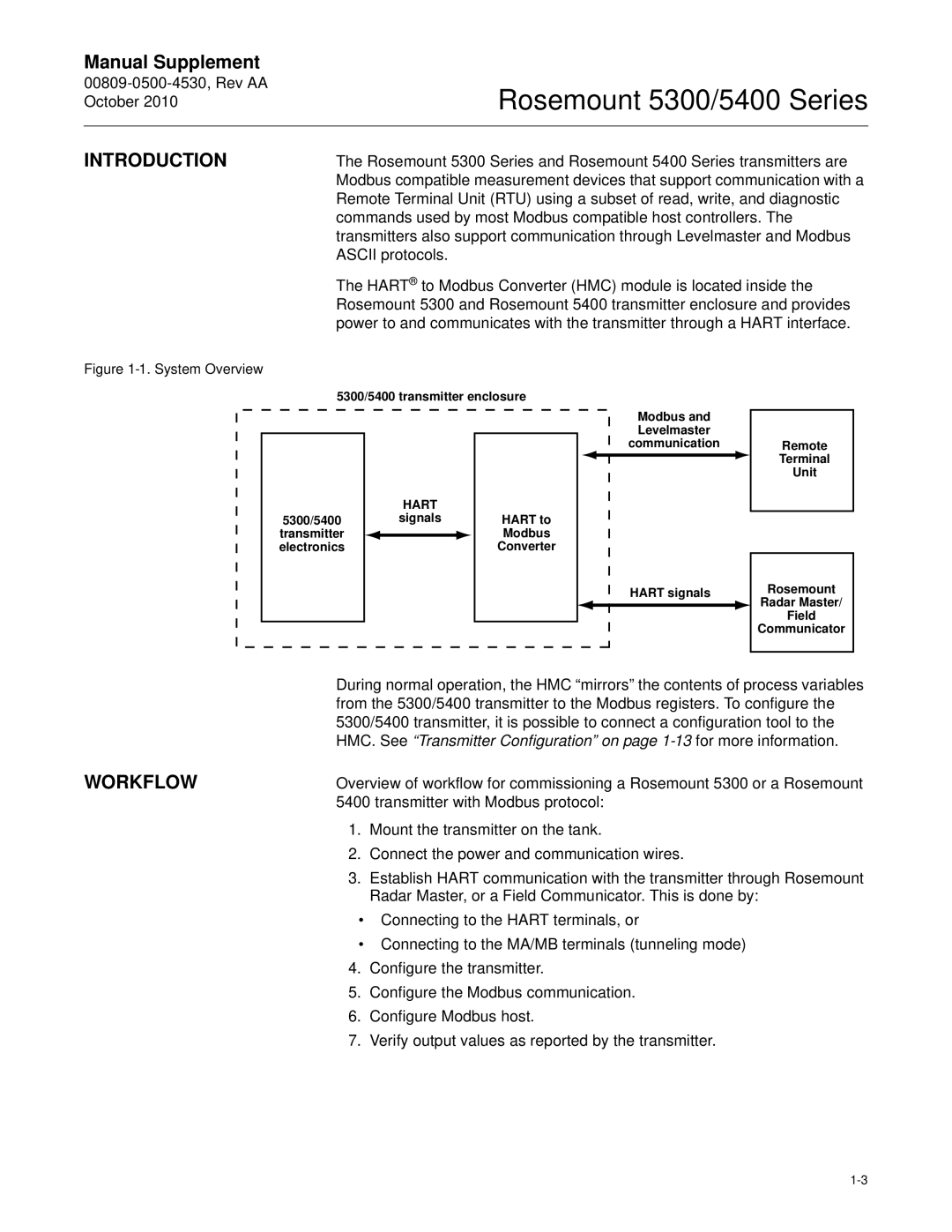
| The HART® to Modbus Converter (HMC) module is located inside the |
| Rosemount 5300 and Rosemount 5400 transmitter enclosure and provides |
| power to and communicates with the transmitter through a HART interface. |
Figure 1-1. System Overview
5300/5400 transmitter enclosure
|
| HART |
| |
5300/5400 |
| signals | HART to | |
transmitter |
|
|
| Modbus |
electronics |
|
|
| Converter |
|
|
|
|
|
Modbus and Levelmaster communication
HART signals
Remote
Terminal
Unit
Rosemount
Radar Master/
Field
Communicator
During normal operation, the HMC “mirrors” the contents of process variables from the 5300/5400 transmitter to the Modbus registers. To configure the 5300/5400 transmitter, it is possible to connect a configuration tool to the HMC. See “Transmitter Configuration” on page
WORKFLOW | Overview of workflow for commissioning a Rosemount 5300 or a Rosemount | |
| 5400 transmitter with Modbus protocol: | |
| 1. | Mount the transmitter on the tank. |
| 2. | Connect the power and communication wires. |
| 3. | Establish HART communication with the transmitter through Rosemount |
|
| Radar Master, or a Field Communicator. This is done by: |
| • Connecting to the HART terminals, or | |
| • Connecting to the MA/MB terminals (tunneling mode) | |
| 4. | Configure the transmitter. |
| 5. | Configure the Modbus communication. |
| 6. | Configure Modbus host. |
| 7. | Verify output values as reported by the transmitter. |
