Manual Supplement
Rosemount 5300/5400 Series
COMMON MODBUS HOST CONFIGURATION
Table
When using Modbus RTU or Modbus ASCII, the registers to receive status and variables must be configured in the host system.
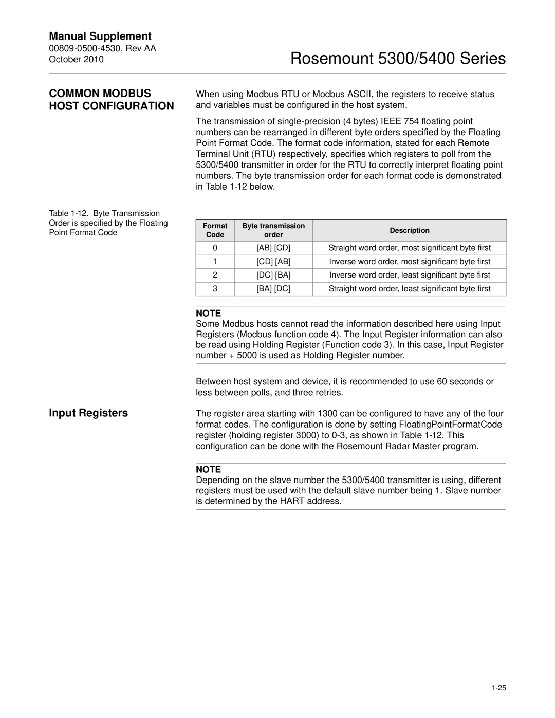
The transmission of
Format | Byte transmission | Description | |
Code | order | ||
| |||
0 | [AB] [CD] | Straight word order, most significant byte first | |
1 | [CD] [AB] | Inverse word order, most significant byte first | |
2 | [DC] [BA] | Inverse word order, least significant byte first | |
3 | [BA] [DC] | Straight word order, least significant byte first | |
|
|
|
Input Registers
NOTE
Some Modbus hosts cannot read the information described here using Input Registers (Modbus function code 4). The Input Register information can also be read using Holding Register (Function code 3). In this case, Input Register number + 5000 is used as Holding Register number.
Between host system and device, it is recommended to use 60 seconds or less between polls, and three retries.
The register area starting with 1300 can be configured to have any of the four format codes. The configuration is done by setting FloatingPointFormatCode register (holding register 3000) to
NOTE
Depending on the slave number the 5300/5400 transmitter is using, different registers must be used with the default slave number being 1. Slave number is determined by the HART address.