For Business-CriticalContinuity
Liebert NX UPS
AC Power
User Manual–40-200kVA, 480V,60Hz
Page
TABLE OF CONTENTS
4.0 OPTIONS
9.0 OPERATING INSTRUCTIONS . . . . . . . . . . . . . . . . . . . . . . . . . . . . . . . . . . . . . . . . . . . . . . .
FIGURES
Figure 39 Main component location drawing Liebert NX 480V, CB2, CB3, CB4 configurations . . . . . . . . .
TABLES
IMPORTANT SAFETY INSTRUCTIONS
SAVE THESE INSTRUCTIONS
Battery Cabinet Precautions
• Remove watches, rings and other metal objects
Requests the user to consult the manual
GLOSSARY OF SYMBOLS
Risk of electrical shock
AC input AC output
1.1External Inspections
1.0INSTALLATION
1.4UPS Location
1.2.1Storing for Delayed Installation
1.2Internal Inspections
1.3Preliminary Checks
1.4.3Special Considerations for Parallel Systems
Battery Location
1.5Considerations in Moving the Liebert NX
1.6Mechanical Considerations
System Composition
1.6.2Floor Installation
1.6.1Clearances
1.6.3Cable Entry
Front of Units
Bypass
Battery Cabinet
Liebert
Liebert NX
Lug Size and Torque Requirements
2.1Power Cabling
2.0ELECTRICAL CONNECTIONS
2.1.1Cable Rating
2.1.3Cabling Guidelines
2.1.2UPS Input Configuration
Figure 4 Input and output busbars
Liebert NX 40-120kVAConnections
Liebert NX 160-200kVAConnections
2.1.4Cable Connections
UPS Rectifier and Bypass Input Supply
2.1.5Safety Ground
2.1.7Cabling Procedure
2.1.6Protective Devices
Common Input Connections
Dual Input Connections
Frequency Converter Mode
2.2.1Monitor Board Features
2.2Control Cables
Figure 5 Monitor board U2
2.3Dry Contacts
Figure 7 Input dry contacts
2.3.2Maintenance Bypass Cabinet Interface
Table 2 Maintenance bypass cabinet interface
2.3.1Input Dry Contacts
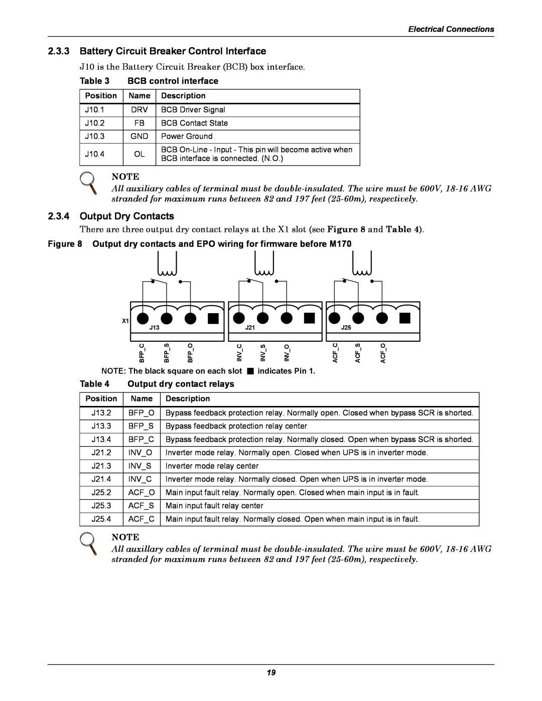
Output dry contact relays
2.3.3Battery Circuit Breaker Control Interface
2.3.4Output Dry Contacts
Table 3 BCB control interface
EPO - NC
Figure 9 EPO wiring
2.3.5EPO Input—Optional
EPO - NO
3.2Safety
3.0BATTERY INSTALLATION
3.1Introduction
3.3External Battery Cabinet Installation
3.3.1Battery Cabinets
Figure 10 Battery cabinets for Liebert NX
3.3.2Connecting the Batteries
3.3.3Installation Considerations
Figure 11 Battery cabinet—details
3.5BCB Shunt Trip
3.3.4Connecting the Battery Cabinet to the UPS
Figure 12 Battery tray and supports
3.4Non-StandardBatteries
3.6Alber Monitoring System—Optional
This power must be UPS protected
4.1.1Performance Requirements
4.1.2LBS Cable and Settings
4.1Load Bus Synchronization
4.0OPTIONS
4.2Configuring Parallel System Operation
4.2.2Features of Parallel System
4.2.1General
480V, 3W UOB Output
480V, 3W Input 480V DC Battery Input
Figure 15 Parallel system block diagram
Liebert NX UPS 40-200kVA
4.2.4Operation Modes Summary
•Battery Mode Operation
•Maintenance Bypass Mode Operation
4.2.3Operating Principles Redundancy Paralleling
4.3.1Conditions for Parallel System
4.3Installing Parallel System
4.3.2Cabinet Installation
4.3.4Power Cables
Auxiliary Dry Contact Cables
For startup procedure, 9.2 - UPS Startup
X2:4
4.3.6Emergency Power Off EPO
Figure 20 Connecting EPO push button
X2:3
5.0UPS SPECIFICATIONS
Environmental characteristics
UPS mechanical characteristics
Table 8 UPS terminal
5.4UPS Electrical Characteristics
Table 10 Input voltage window with derating
Table 9 Rectifier input power
5.4.1Input Rectifier
UPS terminal continued
Table 12 DC intermediate circuit
Table 11 Liebert approved replacement batteries
5.4.2DC Intermediate Circuit
5.4.3Inverter Output
Table 14 Bypass input
5.4.4 Bypass Input
Front
Left Side
Detail A
Front
Parallel Board
2000mm
FRONT VIEW
LEFT VIEW
1239mm
BOTTOM VIEW Front of UPS
TOP VIEW Front of UPS
Installation Drawings
DETAIL A
DETAIL A
224mm
8.83
609.3 24 872.2 34.3
U3819205
TOP VIEW
RIGHT SIDE
FRONT
SECTION A-A
without BCB Cover Plate
Detail A
Top View
Detail B
A D NX 160-200KVAUPS Module Front View A CBB D CD
49 Battery Cabinet Right-SideViews
Auxiliary Contacts
Front
Top Right Side
845 33.2 965 38 2000 78.7
Front
Right Side
UPS Output
Front
Rear
System Input
Without Covers
Kirk-Key
FRONT
UPS Output Breakers Ground Busbar
System
FRONT
Door Open
REAR
A B1-B4 FRONT
Without Covers
LEFT SIDE Isometric View
LEFT SIDE Without Exterior Panels 965 38 in 2000
78.7 in
RIGHT SIDE Without Exterior Panels
7.0OPERATION
7.1General Description
Normal Mode
Battery Mode
7.1.1Bypass Supplies
7.1.2Operating Modes
Parallel Redundancy Mode System Expansion
Maintenance Mode
Liquid Crystal Display LCD Mimic display LED2
8.0OPERATOR CONTROL AND DISPLAY PANEL
8.1.1Display Panel Layout
Figure 45 Overview of control panel
Inverter indicator
Figure 47 Mimic display indicators location
Bypass indicator
Load indicator
Silence On/Off button Inverter On button
Inverter Off button Fault Clear button
Figure 48 Location of control buttons
Button cover EPO button
UPS system
Data and settings
Figure 49 Buzzer location
Figure 50 Sections of the LCD
Table 17 Icons for navigation keys
Figure 51 Menu tree
8.8LCD Menus and Data Items
Operator Control and Display Panel
Figure 52 Language selection
8.9Language Selection
Figure 53 Set date and time
8.10Current Date and Time
History Log records menu
Current
Status
Messages
8.12.1Opening Display
8.12.2Default Screen
Figure 56 Default screen
8.12Types of LCD Screens
Figure 57 Help screen
Press any key back to main menu
8.12.3UPS Help Screen
8.12.4Screen Saver Window
8.13.3System Self-Test
8.13.4 Battery Capacity Test Confirmation
8.13.5Battery Self-TestAborted, Condition Not Met
8.13Pop-UpWindows
9.1Liebert NX Operating Modes
9.0OPERATING INSTRUCTIONS
Table 20 UPS operating modes
Figure 59 Circuit breakers
9.2.1Startup Procedure
9.2UPS Startup
9.1.1Circuit Breakers
•Close CB5 CB1, CB2, CB3 and CB5 are closed
Switch from Bypass Mode to Normal Mode
Switch from Normal Mode to Bypass Mode
9.5Emergency Shutdown With EPO
9.4Auto Restart
9.7.2Battery End-of-DischargeEOD Protection
9.7Battery Protection
9.8Multi-ModuleSystem Procedures
9.7.1Battery Undervoltage Pre-Warning
3.Close Input breaker CB1
9.10Parallel System Startup
9.9Commissioning a Parallel System
10.1.1Analog Input Interface
10.1.2Power Output
10.1Communication and Other User Terminals
10.0OPTIONS
10.1.5Configuring Baud Rates
10.1.4Communication and Monitoring
Table 21 Liebert NX communication options
Figure 62 Liebert IntelliSlot Web card display
Table 22 Relay Card pin configuration
Table 23 Relay card jumper configuration
Relay Card
Figure 63 MultiPort 4 card pin assignment
MultiPort 4 Card
10.3Replacing Dust Filters
10.2.1Remote Alarm Monitor
Figure 64 Dust filter replacement
10.2LBS Mode—LoadBus Synchronization
Specifications and Technical Data
11.0SPECIFICATIONS AND TECHNICAL DATA
Table 24 Torque specifications
Table 25 Battery torque rating
Table 27 Parallel system current table
11.3Cable size and tightening torques
Specifications and Technical Data
11.4Battery Run Times
Table 37 Enersys battery run times in minutes
Table 38 C&D Dynasty battery run times in minutes
Specifications and Technical Data
APPENDIX A - UPS STATUS MESSAGES
Table 39 UPS status messages
UPS Status Messages
Description / Suggested Action if any
Table 39 UPS status messages
UPS Status Messages
Event Message
UPS Status Messages
Table 39 UPS status messages
UPS Status Messages
Table 39 UPS status messages
UPS Status Messages
Table 39 UPS status messages
UPS Status Messages
Page
reducedcapitalequipment andoperatingcosts
Ensuring The High Availability
Of Mission-CriticalData And Applications
Technical Support/ Service