Introduction
1.8Typical Sequence
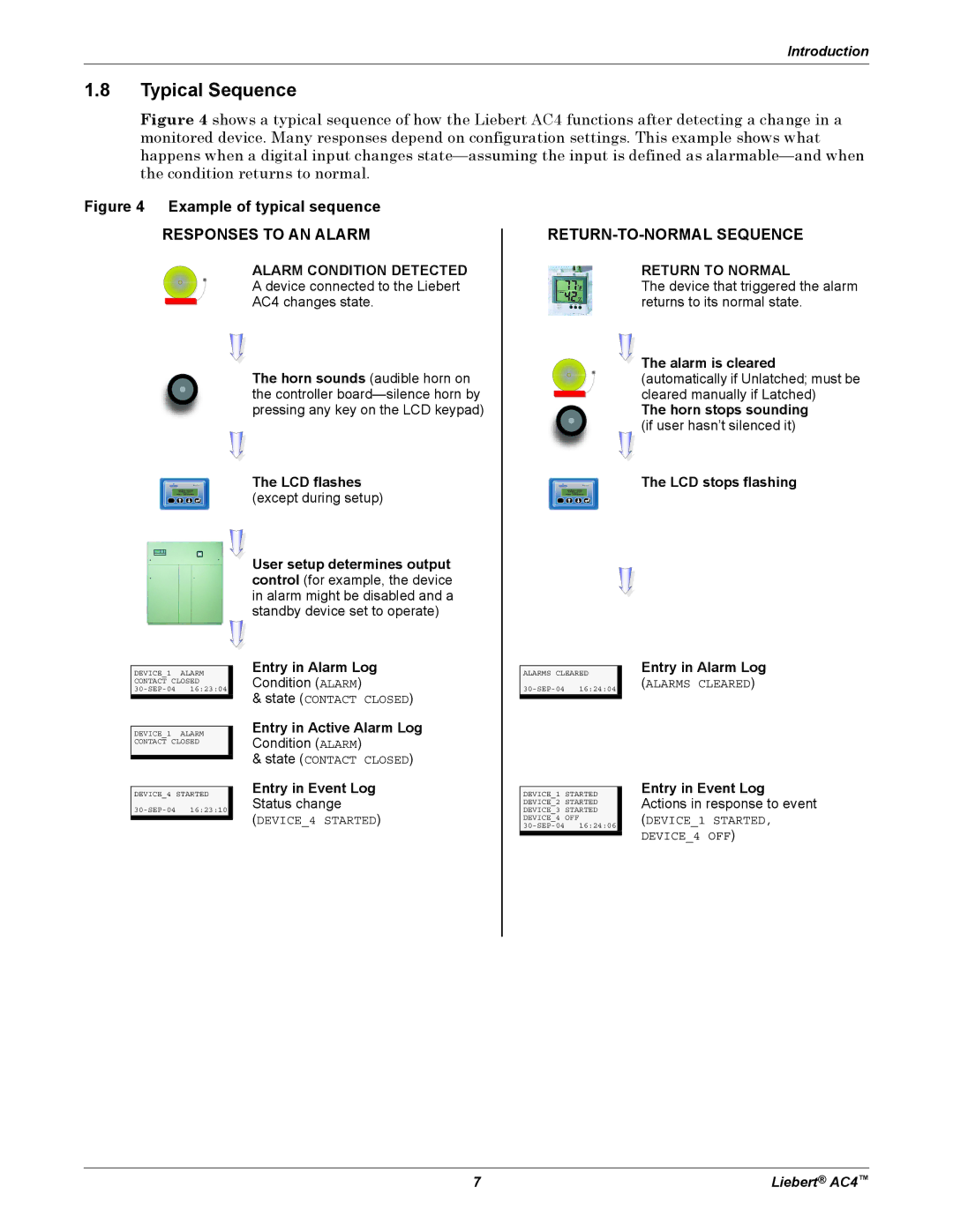
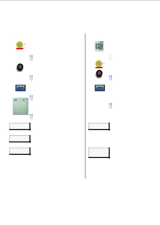
Figure 4 shows a typical sequence of how the Liebert AC4 functions after detecting a change in a monitored device. Many responses depend on configuration settings. This example shows what happens when a digital input changes state—assuming the input is defined as alarmable—and when the condition returns to normal.
Figure 4 Example of typical sequence
RESPONSES TO AN ALARM
ALARM CONDITION DETECTED
A device connected to the Liebert
AC4 changes state.
The horn sounds (audible horn on the controller
The LCD flashes
ESC | (except during setup) |
RETURN-TO-NORMAL SEQUENCE
RETURN TO NORMAL
The device that triggered the alarm returns to its normal state.
![]() The alarm is cleared (automatically if Unlatched; must be cleared manually if Latched)
The alarm is cleared (automatically if Unlatched; must be cleared manually if Latched)
The horn stops sounding
(if user hasn’t silenced it)
The LCD stops flashing
ESC
DEVICE_1 ALARM
CONTACT CLOSED
DEVICE_1 ALARM
CONTACT CLOSED
DEVICE_4 STARTED
User setup determines output control (for example, the device in alarm might be disabled and a standby device set to operate)
Entry in Alarm Log
Condition (ALARM)
&state (CONTACT CLOSED)
Entry in Active Alarm Log
Condition (ALARM)
&state (CONTACT CLOSED)
Entry in Event Log
Status change
(DEVICE_4 STARTED)
ALARMS CLEARED
DEVICE_1 STARTED DEVICE_2 STARTED DEVICE_3 STARTED DEVICE_4 OFF
Entry in Alarm Log
(ALARMS CLEARED)
Entry in Event Log Actions in response to event
(DEVICE_1 STARTED, DEVICE_4 OFF)
7 | Liebert® AC4™ |