Wiring and Connections
3.2Connecting Digital Inputs and Outputs
The digital inputs and outputs are on the lower right side of the Liebert AC4 printed wiring assembly board. This section describes how to connect devices to the Liebert AC4’s inputs and outputs.
Each input is tied to an output with the same number:
•Input 1 is tied to Output 1 (default name: Device_1)
•Input 2 is tied to Output 2 (default name: Device_2)
•Input 3 is tied to Output 3 (default name: Device_3)
•Input 4 is tied to Output 4 (default name: Device_4)
Up to four devices may be connected to the Liebert AC4. Each device must be connected to an input and an output with the same number.
To determine the proper wire size, see Table 4 Wiring specifications.
NOTE
Each terminal block is a removable assembly to permit easier connection of more than one input or output at a time. If making multiple connections, grasp the upper portion of a block and pull firmly until the assembly pulls apart.
After making the connections, push the removed piece back into the portion attached to the printed wiring assembly until the terminal block pieces lock together.
Connecting Liebert Precision Cooling Units
For Liebert Precision Cooling units, follow these steps (be sure to connect the same device to inputs and outputs with the same number (Input 1 and Output 1, Input 2 and Output 2, and so on):
•Connect a digital input from the Liebert AC4 to the Common Alarm Relay of the environmental unit: terminals 75/76 or
•Connect a digital output (numbered the same as the input) from the Liebert AC4 to the Remote Shutdown (Power Control) of the environmental unit: terminal 37/38 or
3.2.1Connecting Digital Inputs
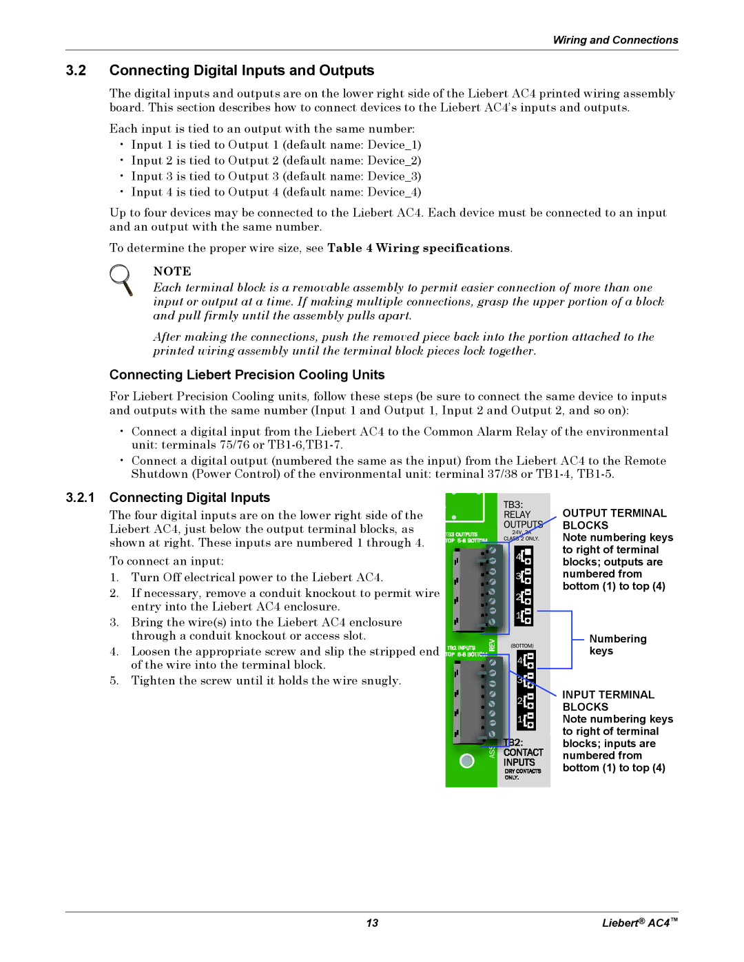
The four digital inputs are on the lower right side of the Liebert AC4, just below the output terminal blocks, as shown at right. These inputs are numbered 1 through 4.
To connect an input:
1.Turn Off electrical power to the Liebert AC4.
2.If necessary, remove a conduit knockout to permit wire entry into the Liebert AC4 enclosure.
3.Bring the wire(s) into the Liebert AC4 enclosure through a conduit knockout or access slot.
4.Loosen the appropriate screw and slip the stripped end of the wire into the terminal block.
5.Tighten the screw until it holds the wire snugly.
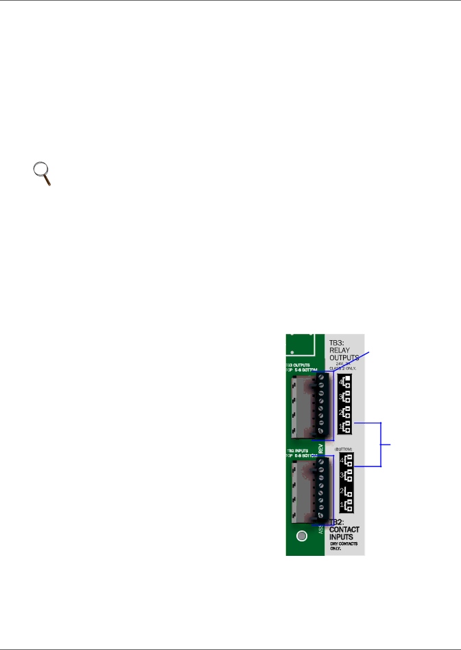
OUTPUT TERMINAL BLOCKS
Note numbering keys to right of terminal blocks; outputs are numbered from bottom (1) to top (4)
Numbering keys
![]() INPUT TERMINAL
INPUT TERMINAL
BLOCKS
Note numbering keys
to right of terminal
blocks; inputs are numbered from bottom (1) to top (4)
13 | Liebert® AC4™ |