Installation Instructions
Figure 10 Low voltage control junction box connections, typical
1 | 2 | 3 | 4 | 5 | 6 | 7 | 8 | 9 | 10 11 12 | 13 14 15 | 16 17 18 | 19 20 21 |
Building
Interface
Relay
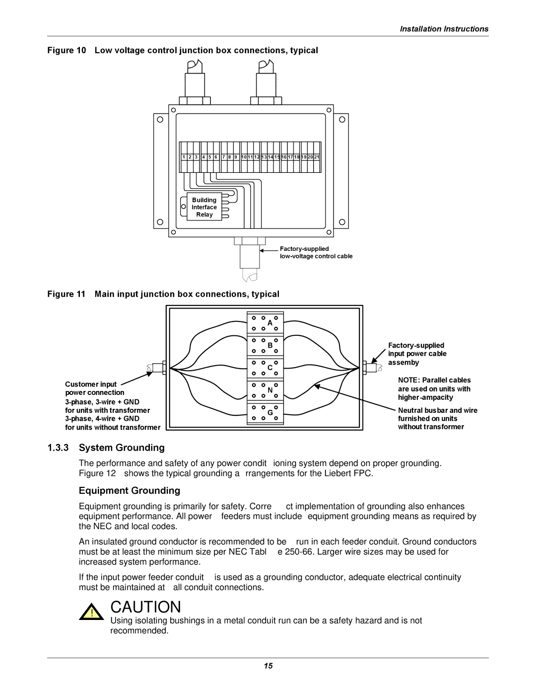
Figure 11 Main input junction box connections, typical
| A |
| B |
| C |
Customer input | N |
power connection | |
| |
for units with transformer | G |
| |
for units without transformer |
|
NOTE: Parallel cables are used on units with
Neutral busbar and wire furnished on units without transformer
1.3.3System Grounding
The performance and safety of any power conditioning system depend on proper grounding. Figure 12 shows the typical grounding arrangements for the Liebert FPC.
Equipment Grounding
Equipment grounding is primarily for safety. Correct implementation of grounding also enhances equipment performance. All power feeders must include equipment grounding means as required by the NEC and local codes.
An insulated ground conductor is recommended to be run in each feeder conduit. Ground conductors must be at least the minimum size per NEC Table
If the input power feeder conduit is used as a grounding conductor, adequate electrical continuity must be maintained at all conduit connections.
! CAUTION
Using isolating bushings in a metal conduit run can be a safety hazard and is not recommended.
15