Installation Instructions
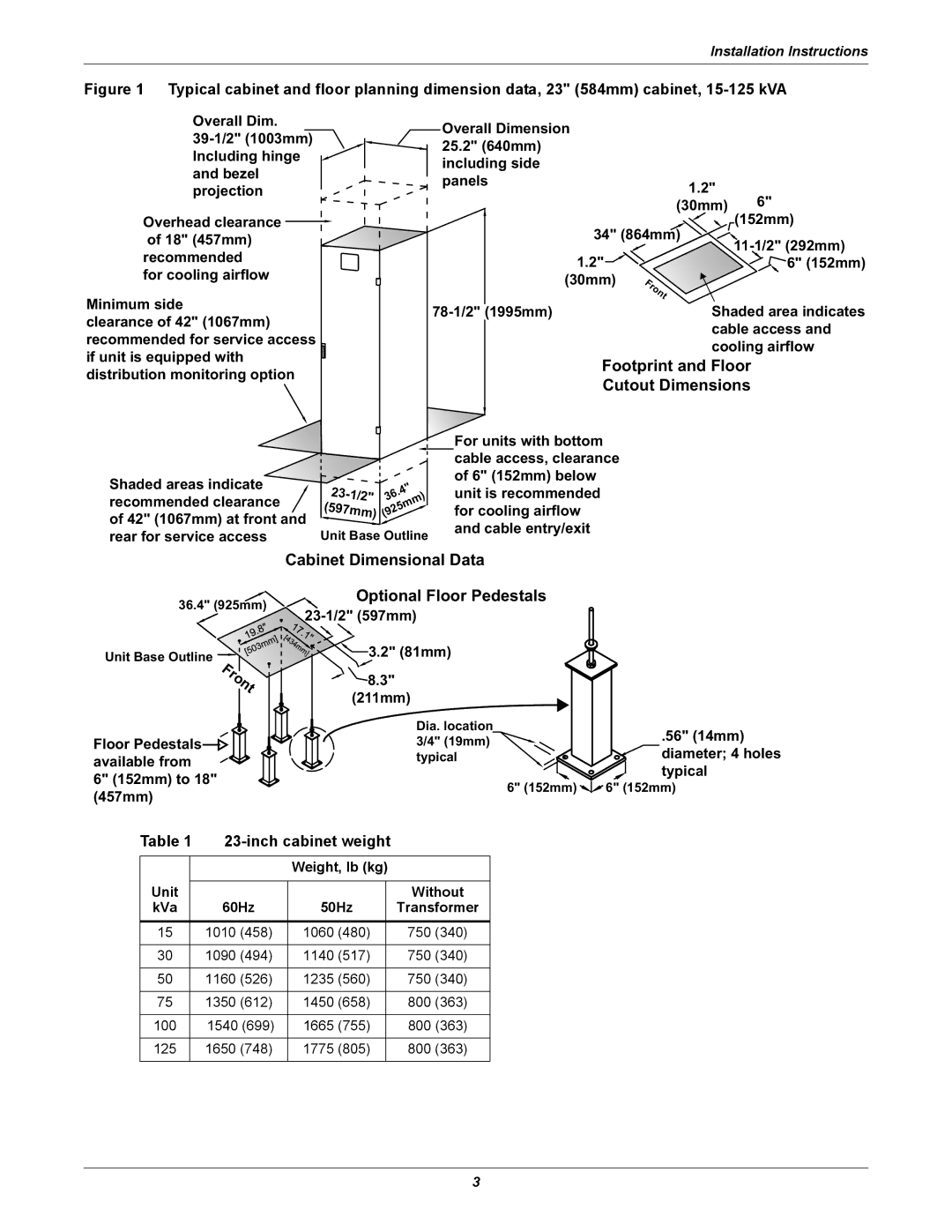
Figure 1 Typical cabinet and floor planning dimension data, 23" (584mm) cabinet, 15-125 kVA
Overall Dim.
Overhead clearance ![]()
of 18" (457mm) recommended
for cooling airflow
Minimum side
clearance of 42" (1067mm) recommended for service access if unit is equipped with distribution monitoring option
Overall Dimension |
|
| |
25.2" (640mm) |
|
| |
including side |
|
| |
panels | 1.2" |
| |
| 6" | ||
| (30mm) | ||
34" (864mm) | (152mm) | ||
1.2" |
| ||
| 6" (152mm) | ||
(30mm) | Front |
| |
|
| ||
Shaded area indicates | |||
| cable access and | ||
| cooling airflow | ||
Footprint and Floor
Cutout Dimensions
Shaded areas indicate recommended clearance ![]() of 42" (1067mm) at front and rear for service access
of 42" (1067mm) at front and rear for service access
23- | .4" | |
36 | ||
1/2" | ||
(597mm) | (925mm) |
Unit Base Outline
For units with bottom cable access, clearance of 6" (152mm) below unit is recommended for cooling airflow and cable entry/exit
Cabinet Dimensional Data
36.4" (925mm)
Unit Base Outline
Front
Floor Pedestals available from 6" (152mm) to 18"
Optional Floor Pedestals
![]()
![]()
![]() 3.2" (81mm)
3.2" (81mm)
![]()
![]() 8.3"
8.3"
(211mm)
Dia. location 3/4" (19mm)![]() typical
typical
.56" (14mm) diameter; 4 holes typical
(457mm)
6" (152mm) ![]()
![]()
![]() 6" (152mm)
6" (152mm)
Table 1 |
|
| |||
|
|
| Weight, lb (kg) |
| |
Unit |
|
|
|
|
|
|
|
|
| Without | |
kVa |
| 60Hz | 50Hz |
| Transformer |
15 |
| 1010 (458) | 1060 (480) |
| 750 (340) |
|
|
|
|
|
|
30 |
| 1090 (494) | 1140 (517) |
| 750 (340) |
|
|
|
|
|
|
50 |
| 1160 (526) | 1235 (560) |
| 750 (340) |
|
|
|
|
|
|
75 |
| 1350 (612) | 1450 (658) |
| 800 (363) |
|
|
|
|
|
|
100 |
| 1540 (699) | 1665 (755) |
| 800 (363) |
|
|
|
|
|
|
125 |
| 1650 (748) | 1775 (805) |
| 800 (363) |
|
|
|
|
|
|
3