Liebert FPC
User Manual - 15 kVA - 300kVA, 3 Phase, 50 & 60 Hz
AC Power
For Business-Critical Continuity
Page
TABLE OF CONTENTS
1.0 INSTALLATION INSTRUCTIONS
3.0 INSPECTION AND STARTUP CHECKLIST
5.0 MAINTENANCE
FIGURES
TABLES
IMPORTANT SAFETY INSTRUCTIONS
Read the entire manual before installing or operating the system
1.1 Unpacking and Installation
1.0 INSTALLATION INSTRUCTIONS
1.1.1 Unpacking and Preliminary Inspection
1.1.2 Handling Considerations
Front
Footprint and Floor Cutout Dimensions
Cabinet Dimensional Data
23-inch cabinet weight
Front
Footprint and Floor cable access and
Cutout Dimensions cooling airflow
47-inch cabinet weight
1.1.3 Unit Preparation
1.1.4 Location Considerations
Figure 3 Recommended minimum service and ventilation clearances
Liebert FPC heat output
1.1.5 Floor Pedestal Installation
Figure 4 Floor pedestal details
1.2 Additional Distribution Mounting & Wiring
1.3 Power and Control Wiring
1.3.1 Input Power Connections
1.2.1 Liebert FDC Distribution Mounting
Figure 5 Electrical connection location for 23 584mm cabinet
15006 - Rev
FPC15000 Rev
Square “D” I-Line Panelboard
Detail B Output Ground Busbar Approx. 1/4 Thick
88 22mm
88 22mm
Table 4 Suggested minimum input wire size data
Installation Instructions
Units with Transformers
Transformerless Units
Installation Instructions
Suggested minimum input wire size data continued
Table 5 Main input circuit breaker interrupting rating
1.3.2 Junction Box Installation
Table 6 Main input junction box electrical connections 4 wire
Table 8 Low-voltage control junction box dimensions, typical
Main input power junction box dimensions, typical
1.3.3 System Grounding
Equipment Grounding
Figure 10 Low voltage control junction box connections, typical
Figure 11 Main input junction box connections, typical
1.3.4 Grounding Electrode Conductor for FPCs With Transformer
Signal Reference Grid
Table 10 Minimum grounding electrode conductor size AWG
systemTypical Liebert FPC without transformer grounding
Typical Liebert FPC with transformer grounding arrangement
Figure 12 Typical grounding arrangements
1.3.5 Output Power Connections
Installation Instructions
Liebert FPC
Figure 13 Typical Liebert FPC equipment arrangement
Liebert FPC
+24VDC
Unit EPO
24VDC
Low Voltage
Terminal Strip
Figure 15 Typical control wiring for units without monitoring
Wiring
Figure 16 Typical control wiring for units with monitoring
Low Voltage Terminal Strip
Factory-Supplied Wiring
Checklists
Warranty
2.1 Internal Inspection
2.2 Startup
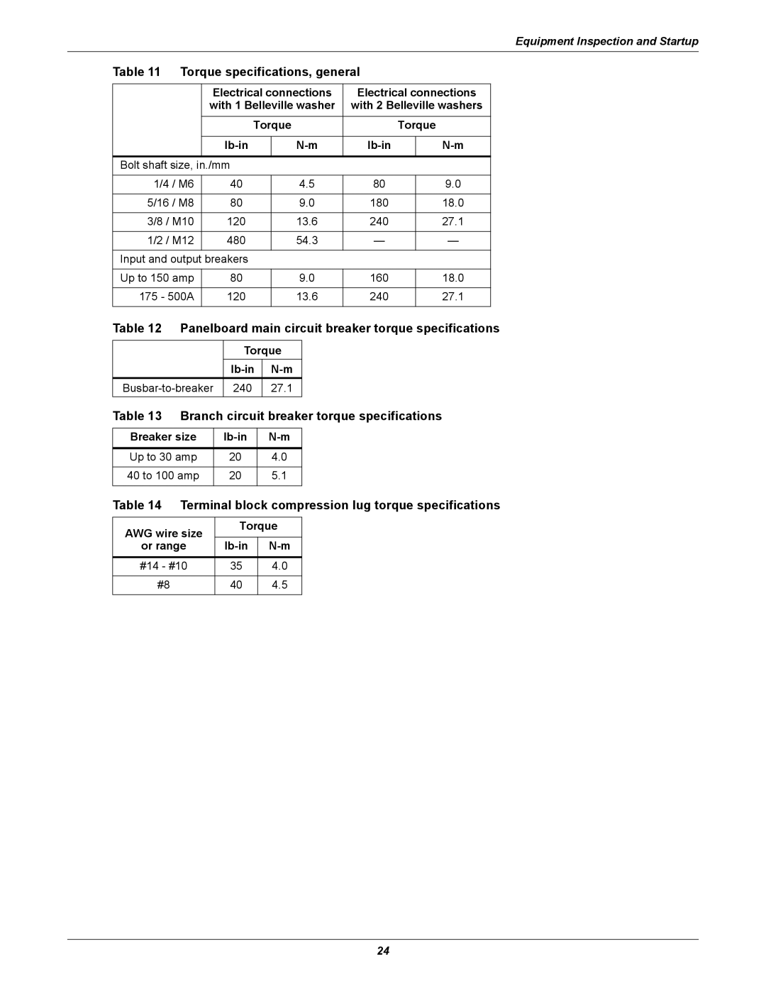
Table 11 Torque specifications, general
Table 12 Panelboard main circuit breaker torque specifications
Table 13 Branch circuit breaker torque specifications
Table 14 Terminal block compression lug torque specifications
3.0 INSPECTION AND STARTUP CHECKLIST
3.1 Inspection
3.2 Startup
Basic Indicators
Power Monitor Panel
3.3 Monitoring System Check-Out
Manual Restart Check
Customer Alarms
3.4 Equipment Connection Check-Out of Units With Distribution Cables
4.1 Startup Procedures
4.1.1 Emergency Shutdown-If Emergency Power Off switch is supplied
4.0 OPERATING INSTRUCTIONS
4.1.2 Normal System Shutdown
4.3 Power Monitor Panel
Alarm Present/Silence
4.2 Basic Monitor Panel Units Without Monitoring
Figure 18 Power monitor panel
Alarms - Upon occurrence of any of the following alarms, the alarm message appears on the LCD dis- play, the Alarm Present/Silence switch is illuminated, and the audible alarm is activated. Pressing the “Alarm Present/Silence” switch silences the audible alarm. After the alarm condition is corrected, the alarm can be reset by pressing the “Alarm Present/Silence” switch when prompted by the LCD display or by way of any Central Monitoring System
Table 15 ASCII interface default parameters
Table 16 RS-232 ASCII port customer commands
Table 17 Monitored parameters data definitions
Operating Instructions
Field #
Data item
5.2 Inspection and Cleaning
5.0 MAINTENANCE
5.1 Repair
5.2.1 Inspection Schedule
Page
Ensuring The High Availability
0f Mission-Critical Data And Applications
Ne t
ti n