Installation Instructions
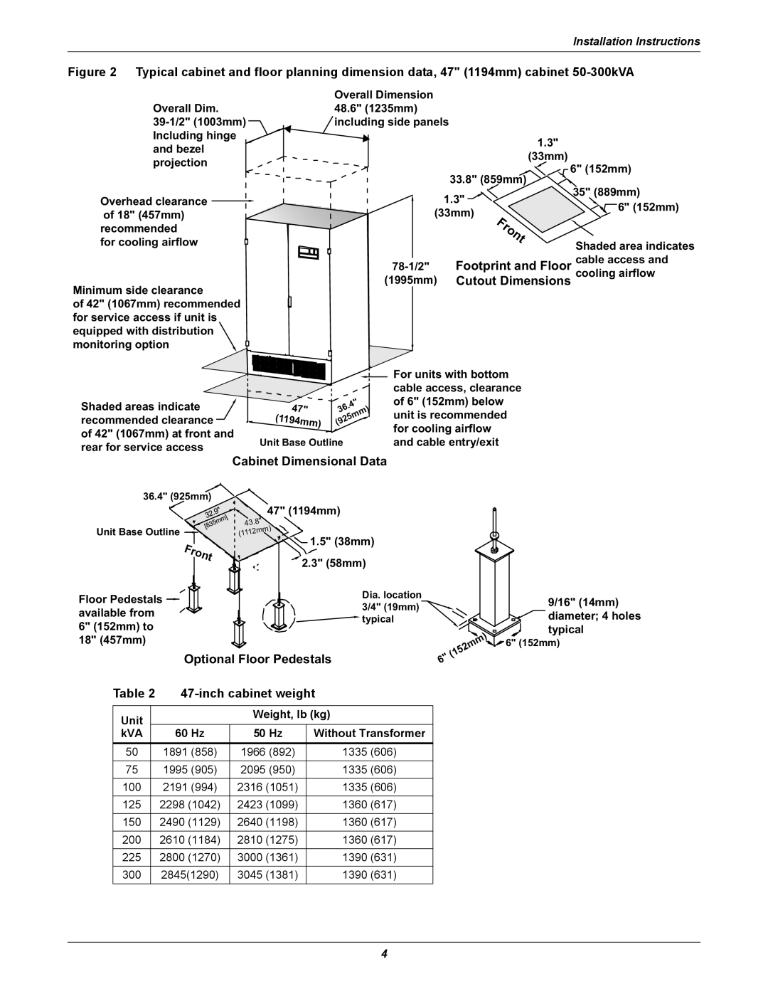
Figure 2 Typical cabinet and floor planning dimension data, 47" (1194mm) cabinet 50-300kVA
Overall Dim.
![]() and bezel
and bezel
projection
Overhead clearance ![]()
of 18" (457mm) recommended
for cooling airflow
Minimum side clearance
of 42" (1067mm) recommended for service access if unit is equipped with distribution monitoring option
Overall Dimension 48.6" (1235mm) ![]() including side panels
including side panels
|
| 1.3" | |
|
| (33mm) | |
| 33.8" (859mm) | 6" (152mm) | |
| 35" (889mm) | ||
| 1.3" | ||
| 6" (152mm) | ||
(33mm) | |||
| |||
| Front | Shaded area indicates | |
|
| ||
Footprint and Floor cable access and | |||
(1995mm) | Cutout Dimensions cooling airflow | ||
Shaded areas indicate | 47" | .4" |
36 | ||
recommended clearance | (1194mm) | (925mm) |
of 42" (1067mm) at front and
rear for service access | Unit Base Outline | |
Cabinet Dimensional Data | ||
|
For units with bottom cable access, clearance of 6" (152mm) below unit is recommended for cooling airflow and cable entry/exit
36.4" (925mm)
Unit Base Outline ![]()
Front
![]() 47" (1194mm) 43.8"
47" (1194mm) 43.8"
(1112mm) ![]()
![]() 1.5" (38mm)
1.5" (38mm)
2.3" (58mm)
Floor Pedestals | Dia. location | |
available from | 3/4" (19mm) | |
typical | ||
6" (152mm) to | ||
| ||
18" (457mm) |
|
Optional Floor Pedestals
(152mm)![]() 6"
6"
9/16" (14mm) diameter; 4 holes typical
6" (152mm)
Table 2 |
| |||
|
|
|
|
|
Unit |
|
| Weight, lb (kg) | |
|
|
|
| |
kVA |
| 60 Hz | 50 Hz | Without Transformer |
|
|
|
|
|
50 |
| 1891 (858) | 1966 (892) | 1335 (606) |
75 |
| 1995 (905) | 2095 (950) | 1335 (606) |
100 |
| 2191 (994) | 2316 (1051) | 1335 (606) |
125 |
| 2298 (1042) | 2423 (1099) | 1360 (617) |
150 |
| 2490 (1129) | 2640 (1198) | 1360 (617) |
200 |
| 2610 (1184) | 2810 (1275) | 1360 (617) |
225 |
| 2800 (1270) | 3000 (1361) | 1390 (631) |
300 |
| 2845(1290) | 3045 (1381) | 1390 (631) |
4
