Installation Instructions
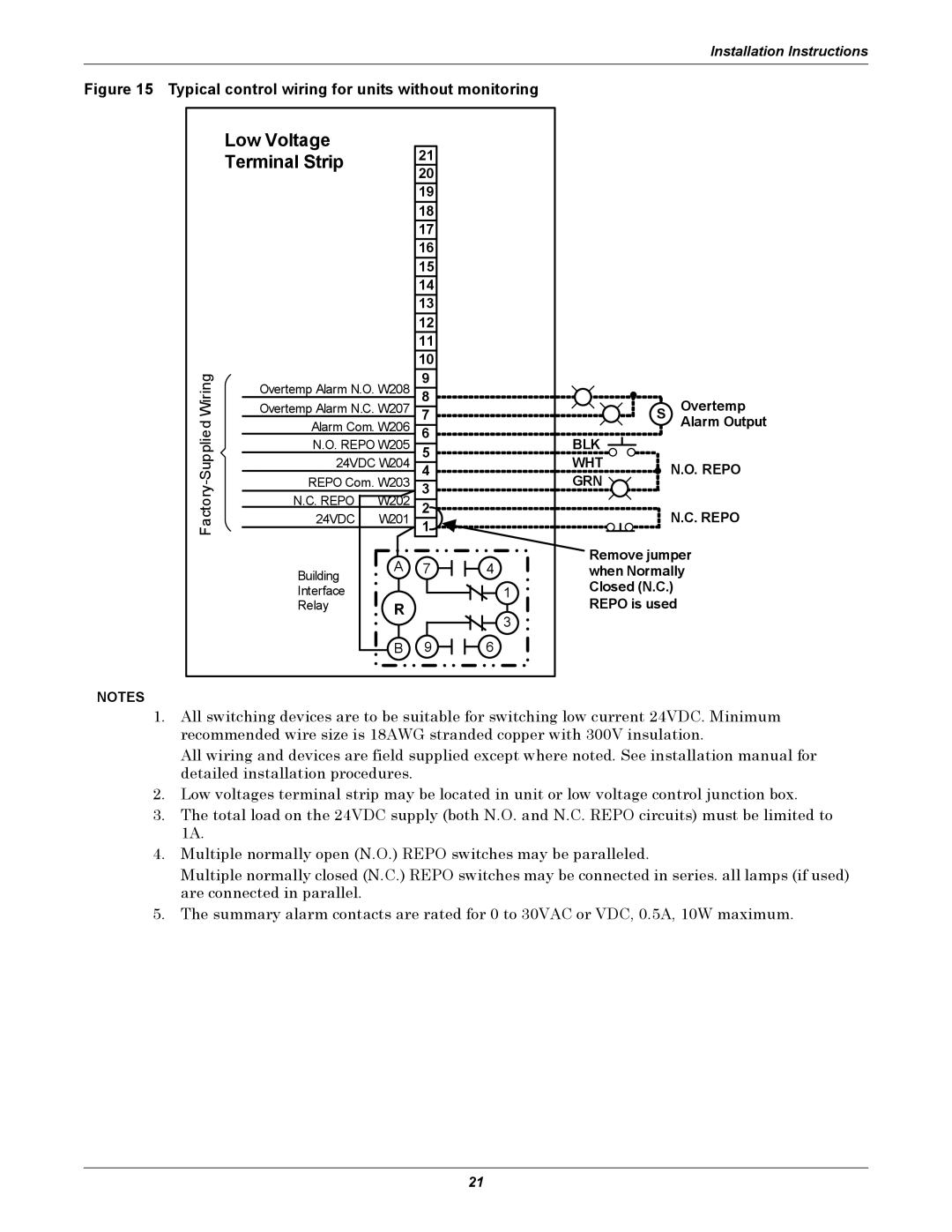
Figure 15 Typical control wiring for units without monitoring
| Low Voltage |
| 21 |
|
| Terminal Strip |
|
| |
|
| 20 |
| |
|
|
|
| |
|
|
| 19 |
|
|
|
| 18 |
|
|
|
| 17 |
|
|
|
| 16 |
|
|
|
| 15 |
|
|
|
| 14 |
|
|
|
| 13 |
|
|
|
| 12 |
|
|
|
| 11 |
|
|
|
| 10 |
|
Wiring | Overtemp Alarm N.O. W208 | 9 |
| |
8 |
| |||
Overtemp Alarm N.C. W207 | 7 |
| ||
Alarm Com. W206 | 6 |
| ||
N.O. REPO W205 | 5 |
| ||
24VDC W204 | 4 |
| ||
REPO Com. W203 | 3 |
| ||
Factory |
| |||
N.C. REPO | W202 | 2 |
| |
24VDC | W201 | 1 |
| |
| Building | A | 7 | 4 |
|
|
|
| |
| Interface |
|
| 1 |
| Relay | R |
| 3 |
|
|
|
| |
|
| B | 9 | 6 |
S Overtemp
Alarm Output
BLK
WHT![]()
![]()
![]()
![]()
![]()
![]()
![]()
![]()
![]()
![]()
![]()
![]()
![]()
![]()
![]()
![]()
![]()
![]()
![]()
![]()
![]() N.O. REPO GRN
N.O. REPO GRN ![]()
![]()
N.C. REPO
Remove jumper when Normally Closed (N.C.)
REPO is used
NOTES
1.All switching devices are to be suitable for switching low current 24VDC. Minimum recommended wire size is 18AWG stranded copper with 300V insulation.
All wiring and devices are field supplied except where noted. See installation manual for detailed installation procedures.
2.Low voltages terminal strip may be located in unit or low voltage control junction box.
3.The total load on the 24VDC supply (both N.O. and N.C. REPO circuits) must be limited to 1A.
4.Multiple normally open (N.O.) REPO switches may be paralleled.
Multiple normally closed (N.C.) REPO switches may be connected in series. all lamps (if used) are connected in parallel.
5.The summary alarm contacts are rated for 0 to 30VAC or VDC, 0.5A, 10W maximum.
21