Installation Instructions
1.3.2Junction Box Installation
Main input (power) and
The junction boxes, if used, can either be shipped with the system or can be
Liebert supplies flexible,
Liebert recommends centering the junction boxes under a floor tile that is easily removed.
Junction box connections must be installed in compliance with the NEC and all other applicable codes.
! WARNING
Verify that incoming line voltage (power) and
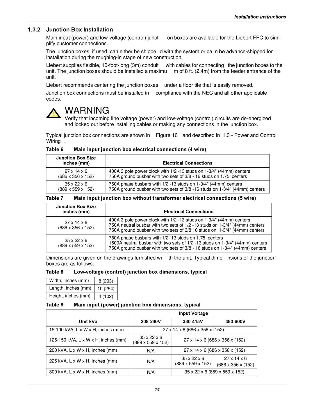
Typical junction box connections are shown in Figure 16 and described in 1.3 - Power and Control Wiring.
Table 6 Main input junction box electrical connections (4 wire)
Junction Box Size |
|
Inches (mm) | Electrical Connections |
|
|
27 x 14 x 6 | 400A 3 pole power block with 1/2 |
(686 x 356 x 152) | 750A ground busbar with two sets of 3/8 - 16 studs on 1.75” centers |
35 x 22 x 6 | 750A phase busbars with 1/2 |
(889 x 559 x 152) | 750A ground busbar with two sets of 3/8 |
Table 7 | Main input junction box without transformer electrical connections (5 wire) | ||
|
| ||
Junction Box Size |
| ||
Inches (mm) | Electrical Connections | ||
| 27 x 14 x 6 | 400A 3 pole power block with 1/2 | |
| 750A neutral busbar with two sets of 1/2 | ||
(686 x 356 x 152) | |||
750A ground busbar with two sets of | |||
|
| ||
|
|
| |
| 35 x 22 x 6 | 750A phase busbars with 1/2 | |
| 1500A neutral busbar with two sets of 1/2 | ||
(889 x 559 x 152) | |||
750A ground busbar with two sets of 3/8 - 16 studs on | |||
|
| ||
|
|
| |
Dimensions are given on the drawings furnished with the unit. Typical dimensions of the junction boxes are as follows:
Table 8 Low-voltage (control) junction box dimensions, typical
Width, inches (mm) |
| 8 (203) |
|
|
|
|
| ||
Length, inches (mm) |
| 10 (254) |
|
|
|
|
| ||
Height, inches (mm) |
| 4 (102) |
|
|
|
|
| ||
Table 9 | Main input (power) junction box dimensions, typical |
| |||||||
|
|
|
|
|
|
|
|
| |
|
|
|
|
|
|
| Input Voltage |
| |
| Unit kVa |
|
|
|
|
|
| ||
|
|
|
| ||||||
|
|
|
|
| |||||
| 27 x 14 x 6 (686 x 356 x (152) | ||||||||
|
|
|
|
|
|
|
|
| |
35 x 22 x 6 |
| 27 x 14 x 6 (686 x 356 x (152) | |||||||
(889 x 559 x 152) | |||||||||
|
|
|
|
|
|
| |||
200 kVA, L x W x H, inches (mm) | N/A |
| 27 x 14 x 6 (686 x 356 x (152) | ||||||
225 kVA, L x W x H, inches (mm) | N/A |
| 35 x 22 x 6 | 27 x 14 x 6 | |||||
| (889 x 559 x 152) | (686 x 356 x (152) | |||||||
|
|
|
|
|
|
| |||
300 kVA, L x W x H, inches (mm) | N/A |
| 35 x 22 x 6 (889 x 559 x 152) | ||||||
14
