Controls, LEDs and Connectors
The SFP modules can be installed/removed both while the RTM is powered and
The presence and also the type of SFP modules is automatically detected.
When using copper SFP modules, the speed is determined through
802.11Ethernet specification. Optical modules do not support
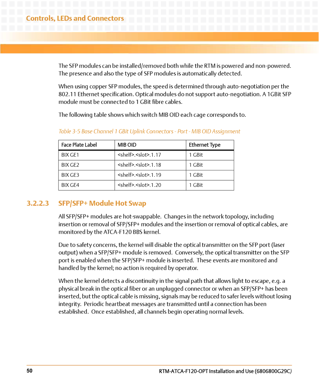
The following table shows which switch MIB OID each cage corresponds to.
Table
Face Plate Label | MIB OID | Ethernet Type |
|
|
|
BIX GE1 | <shelf>.<slot>.1.17 | 1 GBit |
|
|
|
BIX GE2 | <shelf>.<slot>.1.18 | 1 GBit |
|
|
|
BIX GE3 | <shelf>.<slot>.1.19 | 1 GBit |
|
|
|
BIX GE4 | <shelf>.<slot>.1.20 | 1 GBit |
|
|
|
3.2.2.3SFP/SFP+ Module Hot Swap
All SFP/SFP+ modules are
Due to safety concerns, the kernel will disable the optical transmitter on the SFP port (laser output) when a SFP/SFP+ module is removed. Conversely, the optical transmitter on the SFP port is enabled when the SFP/SFP+ module is inserted. These events are monitored and handled by the kernel; no action is required by operator.
When the kernel detects a discontinuity in the signal path that allows light to escape, e.g. a physical break in the optical fiber or an unplugged connector or when an SFP/SFP+ has been inserted, but the optical cable is missing, signals may be reduced to safer levels without losing integrity. Periodic heartbeat messages are transmitted until a connection has been established. Once established, all channels begin operating normal levels.
50 |