Functional Description
4.2Block Diagram
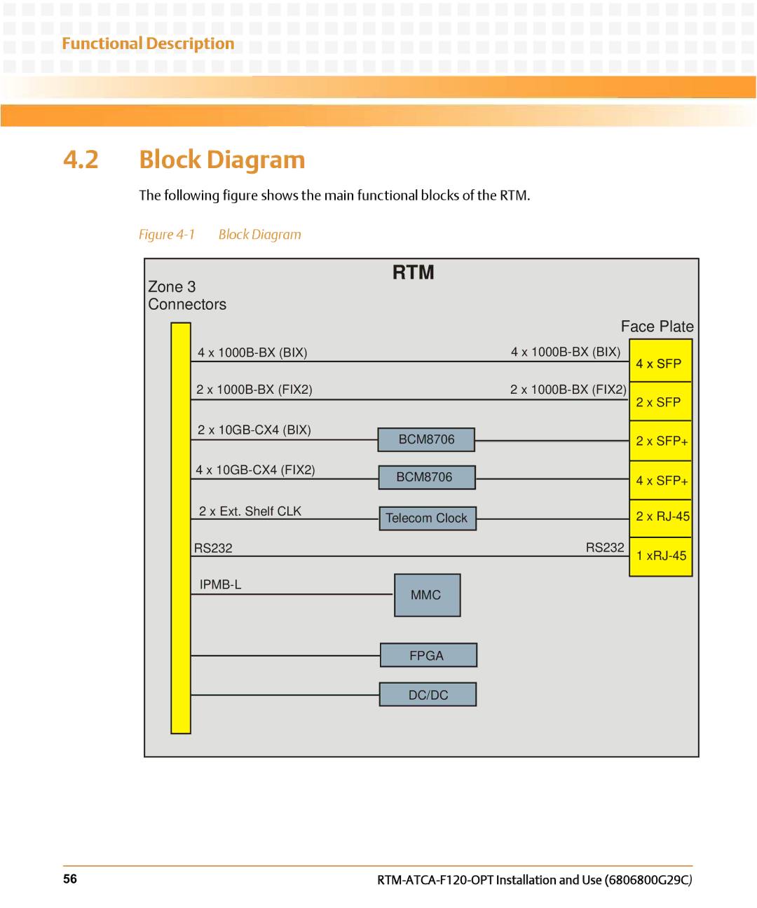
The following figure shows the main functional blocks of the RTM.
Figure 4-1 Block Diagram
Zone 3
Connectors
4 x
RTM
Face Plate
4 x
2 x |
|
|
|
|
|
| 2 x | |||
2 x |
|
|
|
|
|
|
|
|
| |
|
|
|
| BCM8706 |
|
| ||||
|
|
|
|
|
|
| ||||
4 x |
|
|
|
|
|
|
|
| ||
|
|
| BCM8706 |
|
| |||||
|
|
|
|
|
|
| ||||
2 x Ext. Shelf CLK |
|
|
|
|
|
|
|
| ||
Telecoml | Clockl |
| ||||||||
RS232 | RS232 | |||||||||
|
|
|
|
|
| |||||
|
|
|
|
|
|
|
| |||
|
| MMC |
|
|
| |||||
|
|
|
|
|
|
|
| |||
|
|
|
|
|
|
|
|
|
| |
2 x SFP
2 x SFP+
4 x SFP+
2x
1
TelecomFPGAClock
TelecomDC/DClock
56 |