Controls, LEDs and Connectors
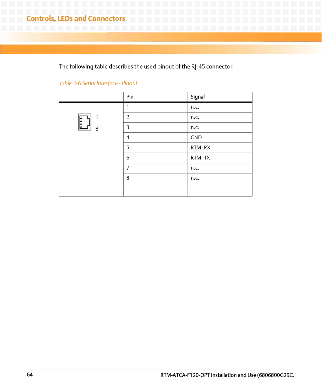
The following table describes the used pinout of the
Table
|
|
| Pin | Signal |
|
|
|
|
|
|
|
| 1 | n.c. |
|
| 1 |
|
|
|
| 2 | n.c. | |
| ||||
|
| |||
|
|
|
|
|
|
|
|
|
|
| 3 | n.c. | ||
|
| 8 | ||
| ||||
|
| |||
|
|
| 4 | GND |
|
|
|
|
|
|
|
| 5 | RTM_RX |
|
|
|
|
|
|
|
| 6 | RTM_TX |
|
|
|
|
|
|
|
| 7 | n.c. |
|
|
|
|
|
|
|
| 8 | n.c. |
|
|
|
|
|
54 |