Controls, LEDs and Connectors
3.2.2.4Telecom Clocking Connectors
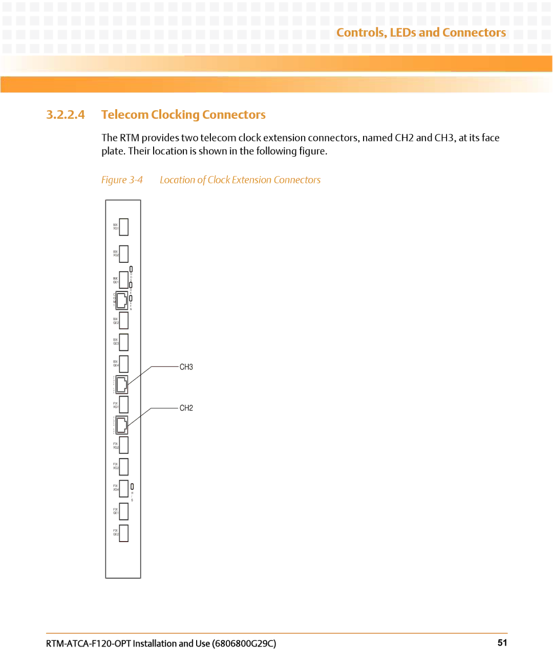
The RTM provides two telecom clock extension connectors, named CH2 and CH3, at its face plate. Their location is shown in the following figure.
Figure 3-4 Location of Clock Extension Connectors
BIX
XG1
BIX
XG2
O
O
S
O
CK
O
MA
1 T
N
BIX
GE2
BIX
GE3
BIX
GE4
C
L
O
C
K
C H 3
FIX
XG1
C
L
O
C
K
C H 2
FIX
XG2
FIX
XG3
FIX
XG4
H
/
S
FIX
GE1
CH3
CH2
FIX
GE2
| 51 |
