Controls, LEDs and Connectors
3.2.1LEDs
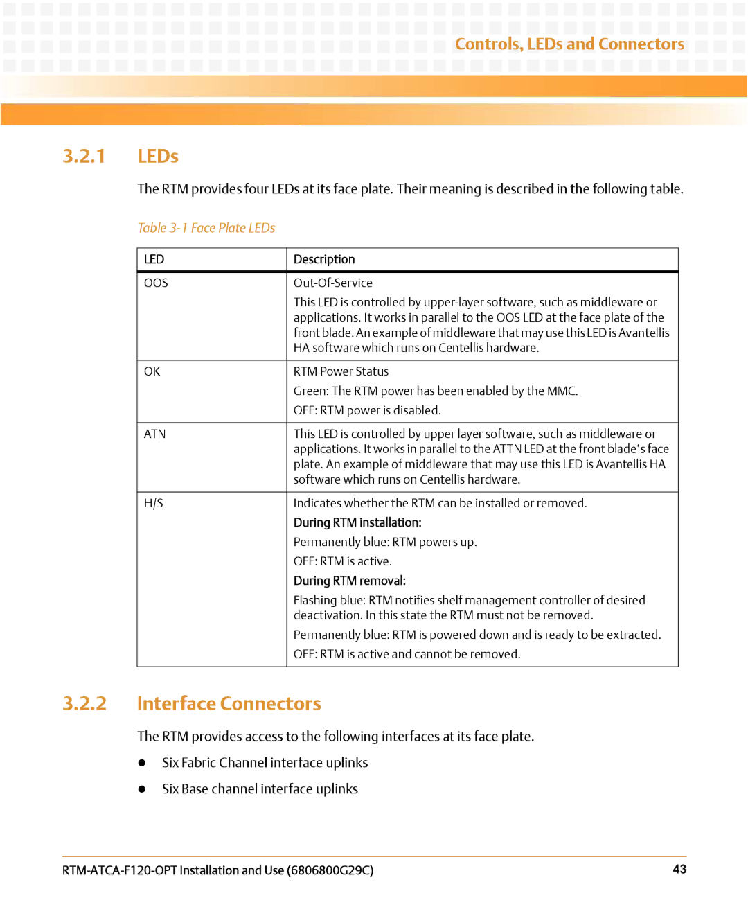
The RTM provides four LEDs at its face plate. Their meaning is described in the following table.
Table 3-1 Face Plate LEDs
LED | Description |
|
|
OOS |
|
| This LED is controlled by |
| applications. It works in parallel to the OOS LED at the face plate of the |
| front blade. An example of middleware that may use this LED is Avantellis |
| HA software which runs on Centellis hardware. |
|
|
OK | RTM Power Status |
| Green: The RTM power has been enabled by the MMC. |
| OFF: RTM power is disabled. |
|
|
ATN | This LED is controlled by upper layer software, such as middleware or |
| applications. It works in parallel to the ATTN LED at the front blade’s face |
| plate. An example of middleware that may use this LED is Avantellis HA |
| software which runs on Centellis hardware. |
|
|
H/S | Indicates whether the RTM can be installed or removed. |
| During RTM installation: |
| Permanently blue: RTM powers up. |
| OFF: RTM is active. |
| During RTM removal: |
| Flashing blue: RTM notifies shelf management controller of desired |
| deactivation. In this state the RTM must not be removed. |
| Permanently blue: RTM is powered down and is ready to be extracted. |
| OFF: RTM is active and cannot be removed. |
|
|
3.2.2Interface Connectors
The RTM provides access to the following interfaces at its face plate.
zSix Fabric Channel interface uplinks
zSix Base channel interface uplinks
| 43 |
