Chapter 14 Removal and replacement of parts
Page 14.3
14.5 Power supply board 1. Undo and remove the four screws which secure the Bezel to the case. Withdraw the Front Panel Assembly
to the limits of the connecting wiring then lay it on top of the case.
2. Pull the Power Supply Board forwards so that it disengages from the connector at the back of the case.
Withdraw the board from the case.
3. Replace all items by reversing this procedure. Take great care to ensure that the cables are not pinched on
re-assembly.
14.6 Connector Board 1. Remove the Rear Panel Assembly as described in Section 14.9.
2. Remove the Mother Board as explained in Section 14.10.
3. Unscrew the threaded hexagonal spacers on top of the Connector Board, then lift the Connector Board off
the studs.
4. Replace all items by reversing this procedure. Take great care to ensure that the cables are not pinched on
re-assembly.
14.7 Fuse 1. Undo and remove the four screws which secure the Bezel to the case. Withdraw the Front Panel Assembly
to the limits of the connecting wiring then lay it on top of the case.
2. Slide the Power Supply Board out of the case.
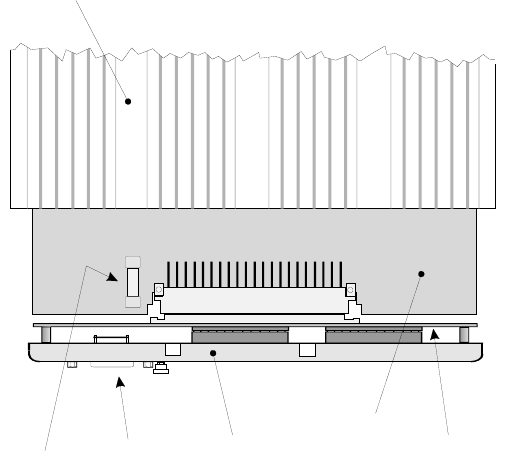
3. Referring to the diagram, find the fuse and gently prise it out of the fuse holder.
4. Press the replacement fuse into the fuse holder. Make sure that the fuse is of the correct type and rating as
specified in Chapter 15.
5. Replace all items in the reverse order of removal. Take great care to ensure that the cables are not pinched
on re-assembly.
Power
Supply
Board
Mother
Board
Rear
Panel
Top of
instrument
case
Socket
SK1
Fuse
Figure 14.4: Where to find the fuse on the Power Supply Board