XDT User’s Manual
3.3.2 Electrical Connections
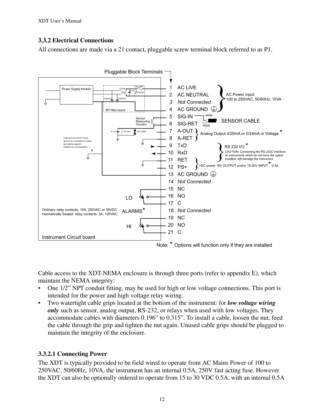
All connections are made via a 21 contact, pluggable screw terminal block referred to as P1.
Pluggable Block Terminals ![]()
Power Supply Module | 0.5A 250V | 1 | AC LIVE |
|
|
4.3mH |
|
| |||
| 0.1uf |
|
|
|
|
| 275VAC | 2 | AC NEUTRAL | AC Power Input: | |
|
| ||||
0.0047uf | 0.0047uf | 3 | Not Connected | 100 to 250VAC, 50/60Hz, 10VA | |
| |||||
|
|
| |||
RFI filter board | 4 | AC GROUND |
| ||
| Sensor | 5 | white |
| |
|
| SENSOR CABLE | |||
| Measuring | 6 |
| ||
| Circuitry | black |
| ||
0.1uf | 1M Ohm 33V 400W | 7 | Analog Output 4/20mA or 0/24mA or Voltage * | ||
|
| ||||
Logic ground and AC Power |
| 8 |
|
|
|
|
|
|
|
| |
ground are connected for safety |
|
|
|
| RS 232 I/O * |
and electromagnetic |
| 9 | TxD |
| |
interference considerations |
|
| |||
|
| 10 | RxD |
| CAUTION: Connecting the |
|
|
| on instruments which do not have the option | ||
|
| 11 | RET |
| |
|
|
| installed, will damage the instrument. | ||
|
| +DC power 15V OUTPUT and/or | |||
|
| 12 | PS+ | ||
|
|
|
| ||
|
| 13 | AC GROUND |
| |
|
| 14 | Not Connected |
| |
|
| 15 | NC |
|
|
| LO | 16 | NO |
|
|
| 17 | C |
|
| |
|
|
|
| ||
Ordinary relay contacts: 10A, 250VAC or 30VDC | ALARMS* | 18 | Not Connected |
| |
Hermetically Sealed relay contacts: 3A, 120VAC |
| ||||
|
| 19 | NC |
|
|
| HI | 20 | NO |
|
|
| 21 | C |
|
| |
|
|
|
| ||
Instrument Circuit board
Note: * Options will function only if they are installed
Cable access to the
•One 1/2” NPT conduit fitting, may be used for high or low voltage connections. This port is intended for the power and high voltage relay wiring.
•Two watertight cable grips located at the bottom of the instrument: for low voltage wiring only such as sensor, analog output,
3.3.2.1 Connecting Power
The XDT is typically provided to be field wired to operate from AC Mains Power of 100 to 250VAC, 50/60Hz, 10VA, the instrument has an internal 0.5A, 250V fast acting fuse. However the XDT can also be optionally ordered to operate from 15 to 30 VDC 0.5A, with an internal 0.5A
12