XDT User’s Manual Appendices
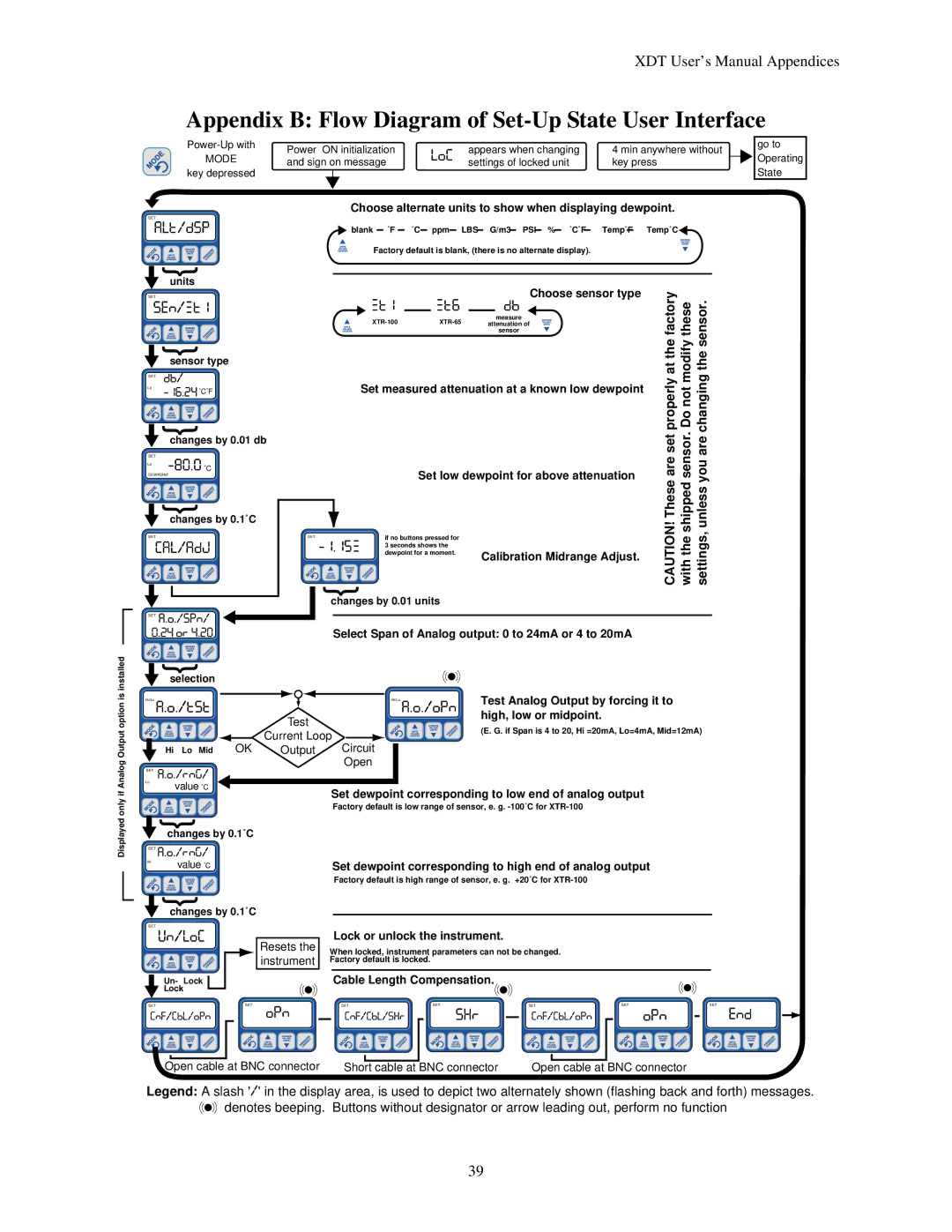
Appendix B: Flow Diagram of Set-Up State User Interface
installed
MODE key depressed
SET
| { |
SETSEN/XT1units | |
| { |
| sensor type |
SET | DB/ |
| |
Lo |
|
| |
| { |
| changes by 0.01 db |
SET
Lo |
|
| |
DEWPOINT | |
| { |
SETCAL/ADJchanges by 0.1˚C | |
SET0.A24.O.OR/SPN/4.20 | |
| { |
| selection |
LOC
Choose alternate units to show when displaying dewpoint.
blank ˚F |
| ˚C |
| ppm LBS |
| G/m3 PSI |
| % |
| ˚C˚F |
|
| Temp˚F Temp˚C |
|
|
|
|
|
| ||||||||
Factory default is blank, (there is no alternate display). |
| ||||||||||||
|
|
|
|
| XT1 |
| XT6 |
| DB | Choose sensor type | CAUTION! These are set properly at the factory with the shipped sensor. Do not modify these settings, unless you are changing the sensor. |
|
|
|
|
|
|
|
| ||||
|
|
|
|
|
|
| measure |
| |||
|
|
|
|
|
| attenuation of |
| ||||
|
|
|
|
|
|
|
|
| sensor |
| |
|
|
|
|
| Set measured attenuation at a known low dewpoint | ||||||
|
|
|
|
|
| Set low dewpoint for above attenuation | |||||
|
|
|
|
|
|
|
|
|
|
| |
|
|
|
|
|
|
|
|
|
|
| |
SET |
| if no buttons pressed for |
|
|
| ||||||
|
|
|
| ||||||||
| 3 seconds shows the |
|
|
| |||||||
| dewpoint for a moment. | Calibration Midrange Adjust. | |||||||||
|
|
|
|
|
|
|
| ||||
| { |
|
|
|
|
|
|
| |||
changes by 0.01 units
Select Span of Analog output: 0 to 24mA or 4 to 20mA
go to
![]() Operating
Operating
State
Displayed only if Analog Output option is
Hi/Lo AA..OO../RNG//TST |
|
| Hi/Lo A.O./OPN | Test Analog Output by forcing it to | |
|
|
| Test |
| high, low or midpoint. |
|
|
|
| (E. G. if Span is 4 to 20, Hi =20mA, Lo=4mA, Mid=12mA) | |
|
|
| Current Loop | ||
| A.O./RNG/ |
|
| ||
| OK | Output | Circuit |
| |
| Hi Lo Mid |
| |||
|
|
|
| Open |
|
SET |
|
|
|
|
|
Lo | value ˚C |
|
|
|
|
|
|
| Set dewpoint corresponding to low end of analog output | ||
|
|
|
| ||
| { |
|
| Factory default is low range of sensor, e. g. | |
|
|
|
|
| |
| changes by 0.1˚C |
|
|
| |
SET
Hi UN/LOCvalue ˚C
{ changes by 0.1˚C
SETCNF/CBL/OPN | SET |
SET |
|
Un- Lock |
|
Lock |
|
ResetsOPNthe instrument
Set dewpoint corresponding to high end of analog output
Factory default is high range of sensor, e. g. +20˚C for
Lock or unlock the instrument.
When locked, instrument parameters can not be changed.
Factory default is locked.
Cable Length Compensation.
SETCNF/CBL/SHR SET SHR SETCNF/CBL/OPN SET OPN SET END
Open cable at BNC connector Short cable at BNC connector | Open cable at BNC connector |
Legend: A slash '/' in the display area, is used to depict two alternately shown (flashing back and forth) messages. ![]() denotes beeping. Buttons without designator or arrow leading out, perform no function
denotes beeping. Buttons without designator or arrow leading out, perform no function
39