Section 3: Instrument
•The instrument will display the measurement using the newly acquired calibration values.
The instrument computes the dewpoint from the measured capacitance of the sensor. The sequence of computations is as follows:
•The capacitance is converted to percent of full scale
•Cal Adj is applied to correct the mid point of the curve.
•If enabled, the
•If enabled, the single point calibration is applied to fine tune the transfer function.
•The corrected percent of full scale is converted to dewpoint.
3.4.4.4 Viewing Serial Number Mode
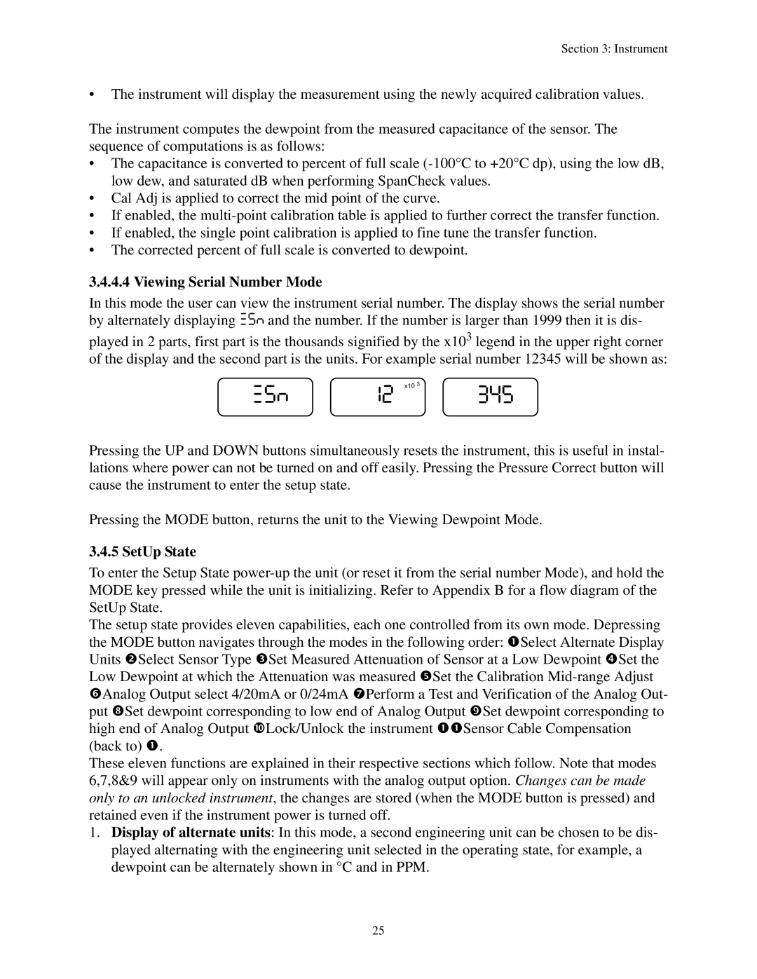
In this mode the user can view the instrument serial number. The display shows the serial number by alternately displaying XSN and the number. If the number is larger than 1999 then it is dis-
played in 2 parts, first part is the thousands signified by the x103 legend in the upper right corner of the display and the second part is the units. For example serial number 12345 will be shown as:
x10 3
Pressing the UP and DOWN buttons simultaneously resets the instrument, this is useful in instal- lations where power can not be turned on and off easily. Pressing the Pressure Correct button will cause the instrument to enter the setup state.
Pressing the MODE button, returns the unit to the Viewing Dewpoint Mode.
3.4.5 SetUp State
To enter the Setup State
The setup state provides eleven capabilities, each one controlled from its own mode. Depressing the MODE button navigates through the modes in the following order: nSelect Alternate Display Units oSelect Sensor Type pSet Measured Attenuation of Sensor at a Low Dewpoint qSet the Low Dewpoint at which the Attenuation was measured rSet the Calibration
These eleven functions are explained in their respective sections which follow. Note that modes 6,7,8&9 will appear only on instruments with the analog output option. Changes can be made only to an unlocked instrument, the changes are stored (when the MODE button is pressed) and retained even if the instrument power is turned off.
1.Display of alternate units: In this mode, a second engineering unit can be chosen to be dis- played alternating with the engineering unit selected in the operating state, for example, a dewpoint can be alternately shown in °C and in PPM.
25