Section 3: Instrument
3.4.4.2 Alarms
There are two independent optional alarms, they are named HI and LO alarms. Each alarm can activate a single pole double throw relay rated at 10A 250VAC or 30VDC per contact. Instru- ments for use in Division 2 Hazardous Areas have hermetically sealed relays rated at 3A 125VAC. Specially ordered instruments may have a third alarm, refer to the supplied addendum for relay contact rating, pinouts and user interface issues. The alarms can be set with a
When an alarm relay is deenergized the corresponding HI and/or LO indicator flashes on the dis- play while viewing the dewpoint.
The behavior of the alarm when a sensor failure (e.g. open or short) is detected is also program- mable. The options upon sensor failure are:
1.Fail High - put the alarm in a state as if the dewpoint is high, e.g. A.X.H
2.Fail Low - put the alarm in a state as if the dewpoint is low, e.g. A.X.L
3.Fail Flashing - Energize/Deenergize the relay alternating once every 2 seconds, e.g. A.X.F
4.No Special Handling - if sensor is open the alarm is in a low dewpoint state; if the sensor is shorted, the alarm is in a high dewpoint state, e.g. A.X.N
Setting or checking the present setup of the alarms is illustrated with the following example:
EXAMPLE : - Set the ‘HI’ alarm to
When following these instructions, it may be helpful to refer to Appendix A.
1.Make sure that the instrument is not in the locked mode.
2.While in the viewing ‘Dewpoint Mode’ push the UP or DOWN buttons until the °C indi- cator appears.
3. Push the MODE button until the display shows: | SET | * | * |
HI |
the asterisks ‘*’ take the place of characters that may appear depending on previous set- tings; the ‘SET’ indicator means that changes can be made; the ‘HI’ indicator means that we are changing the HI Alarm, (alarm #1).
Note that if the instrument does not have the alarm options installed this MODE (User Option) will not appear.
SET
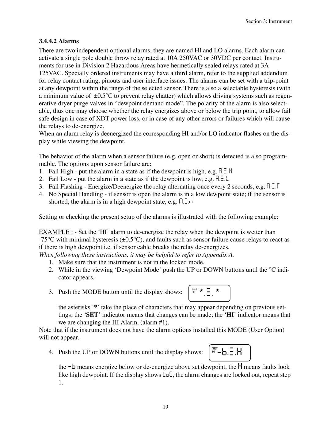
4.Push the UP or DOWN buttons until the display shows: HI
the
19