Section 3: Instrument
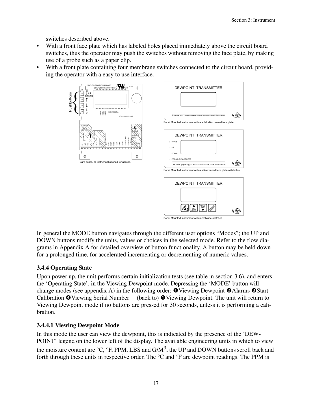
switches described above.
•With a front face plate which has labeled holes placed immediately above the circuit board switches, thus the operator may push the switches without removing the face plate, by making use of a probe such as a paper clip.
•With a front plate containing four membrane switches connected to the circuit board, provid- ing the operator with a easy to use interface.
|
|
|
|
| XDT (C) 1999 XENTAUR CORP. | R | ||||||
|
|
|
| M |
| DEWPOINT TRANSMITTER C | US | |||||
Pushbuttons |
|
|
| O |
| 2000 2001 2002 2003 |
|
|
| |||
|
|
| R |
|
|
|
|
| ||||
| S1 |
|
| D |
|
|
|
|
|
|
| |
|
|
|
| E |
|
|
|
|
|
|
| |
| S2 |
|
|
|
|
|
|
|
|
|
|
|
| S3 |
|
|
|
|
|
|
|
|
|
|
|
|
|
|
|
|
|
|
|
|
|
|
| |
|
|
|
| P |
|
|
|
|
|
| ||
|
|
|
|
|
|
|
|
|
| |||
| S4 |
|
| R |
|
|
| MADE IN USA |
|
| ||
|
|
|
| S |
|
|
|
|
| |||
J.F.M.A.M.J.J.A.S.O.N.D
CAUTION |
|
|
|
|
|
|
|
|
|
|
|
|
|
|
|
RELAY |
|
|
|
|
|
|
|
|
|
|
|
|
|
|
|
VOLTAGE | RELAY |
|
|
|
|
|
|
|
|
|
|
|
|
|
|
|
|
|
|
|
|
|
|
|
|
| |||||
| LOW |
|
|
|
|
|
|
|
|
| 50/60HZ |
| |||
|
|
|
|
|
|
|
|
|
|
| 10VA |
| |||
|
|
|
|
|
|
|
| A.RET | A.OUT |
|
|
| |||
o | o |
|
|
|
|
|
|
|
|
|
| ||||
C RELAYHI NO NC | C | NO | NC | GND | PS+ | RET | RXD | TXD | GND | ACN | ACH | ||||
Bare board, or Instrument opened for access.
DEWPOINT TRANSMITTER
Remove front plate to access control buttons, consult the manual.
Panel Mounted Instrument with a solid silkscreened face plate
DEWPOINT TRANSMITTER
MODE
UP
DOWN
PRESSURE CORRECT
Use probe (paper clip) to push control buttons, consult the manual.
Panel Mounted Instrument with a silkscreened face plate with holes
DEWPOINT TRANSMITTER
CHOICES
VALUES
UNITS
UNITS
MODE
VALUES
CHOICES
PRESSURECORRECT
Panel Mounted Instrument with membrane switches
In general the MODE button navigates through the different user options “Modes”; the UP and DOWN buttons modify the units, values or choices in the selected mode. Refer to the flow dia- grams in Appendix A for detailed overview of button functionality. A button may be held down for a prolonged time, for accelerated incrementing or decrementing of numeric values.
3.4.4 Operating State
Upon power up, the unit performs certain initialization tests (see table in section 3.6), and enters the ‘Operating State’, in the Viewing Dewpoint mode. Depressing the ‘MODE’ button will change modes (see appendix A) in the following order: nViewing Dewpoint oAlarms pStart Calibration qViewing Serial Number (back to) nViewing Dewpoint. The unit will return to Viewing Dewpoint mode if no buttons are pressed for 30 seconds, unless it is performing a cali- bration.
3.4.4.1 Viewing Dewpoint Mode
In this mode the user can view the dewpoint, this is indicated by the presence of the ‘DEW- POINT’ legend on the lower left of the display. The available engineering units in which to view
the moisture content are °C, °F, PPM, LBS and G/M3; the UP and DOWN buttons scroll back and forth through these units in respective order. The °C and °F are dewpoint readings. The PPM is
17