Installation Overview
This overview outlines the basic steps for installing the PoleVault System. Detailed description of these steps is given in five sections, Stages One though Five.
NAdditional installation hardware is needed and should be supplied by the installer. See Introduction, “Items not included” on page
Optional accessories may be desired for this installation. For a list see Introduction, “Optional items”, on page
Refer to local building standards and codes to verify that the installation will meet all the regulatory requirements. Observe all local and national building and safety codes, UL requirements, and ADA Accessibility Guidelines. Refer to the specifications at the end of this guide for system hardware weights and dimensions.
Carefully check inventory of PoleVault system packages, input and output devices, any optional accessories, and installation hardware before commencing.
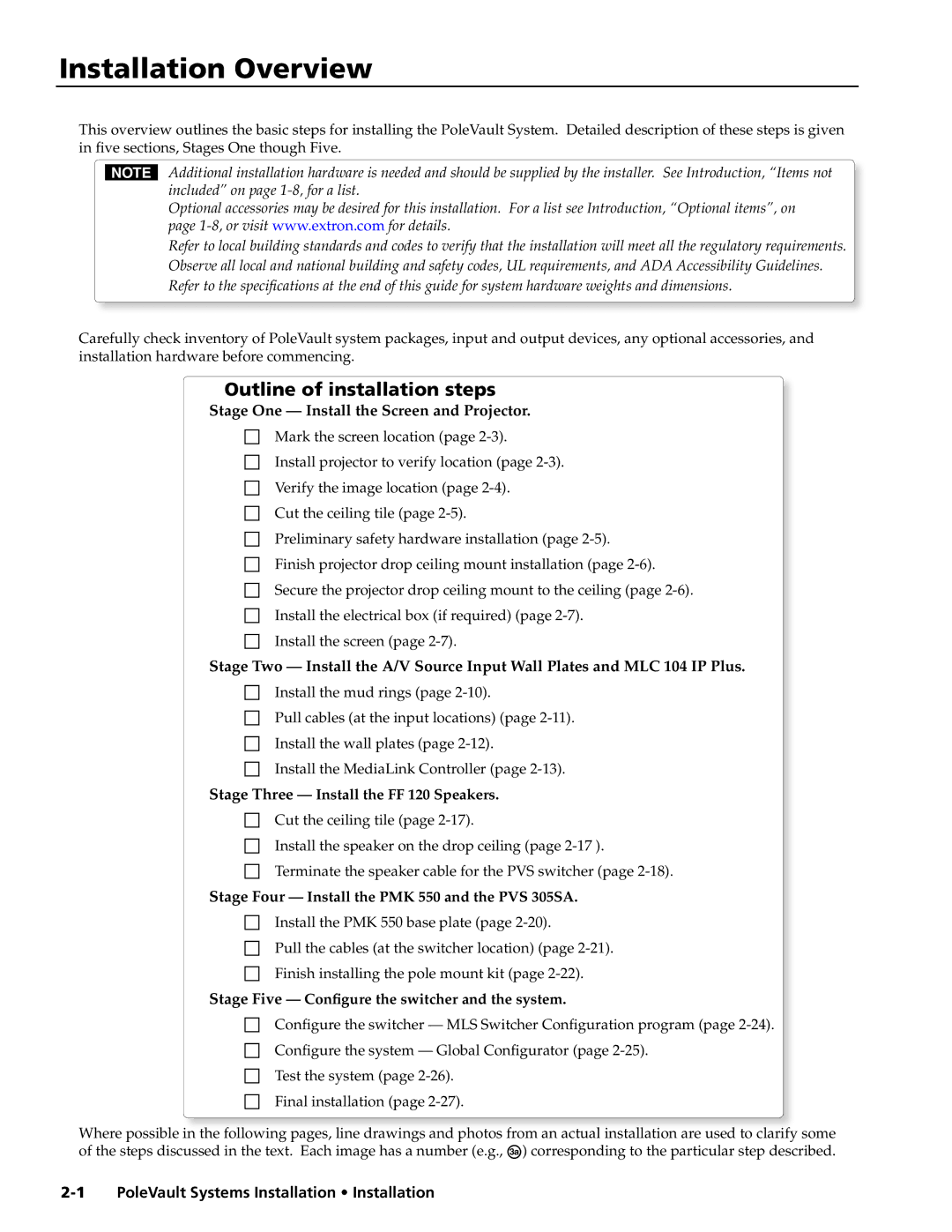
Outline of installation steps
Stage One — Install the Screen and Projector.
cMark the screen location (page
cInstall projector to verify location (page
cVerify the image location (page 2-4).
cCut the ceiling tile (page
cPreliminary safety hardware installation (page
cFinish projector drop ceiling mount installation (page
cSecure the projector drop ceiling mount to the ceiling (page
cInstall the electrical box (if required) (page
cInstall the screen (page
Stage Two — Install the A/V Source Input Wall Plates and MLC 104 IP Plus.
cInstall the mud rings (page 2-10).
cPull cables (at the input locations) (page
cInstall the wall plates (page
cInstall the MediaLink Controller (page
Stage Three — Install the FF 120 Speakers.
cCut the ceiling tile (page
cInstall the speaker on the drop ceiling (page
cTerminate the speaker cable for the PVS switcher (page
Stage Four — Install the PMK 550 and the PVS 305SA.
cInstall the PMK 550 base plate (page
cPull the cables (at the switcher location) (page
cFinish installing the pole mount kit (page
Stage Five — Configure the switcher and the system.
cConfigure the switcher — MLS Switcher Configuration program (page
cConfigure the system — Global Configurator (page
cTest the system (page 2-26).
cFinal installation (page 2-27).
Where possible in the following pages, line drawings and photos from an actual installation are used to clarify some of the steps discussed in the text. Each image has a number (e.g., Ñ) corresponding to the particular step described.