Installation — Stage Five, cont’d
d.Test the controller’s configuration with the following:
•Check that the MLC is controlling the PVS 305SA switcher and projector, and output’s the correct image when switching inputs.
•Check the projector’s power control (turn it off and on at the MLC controller).
•Adjust the configuration as necessary.
e.Adjust the audio input sensitivity as follows:
•Ensure there is an audio source at each transmitter.
•Set the MLC controller’s volume to maximum.
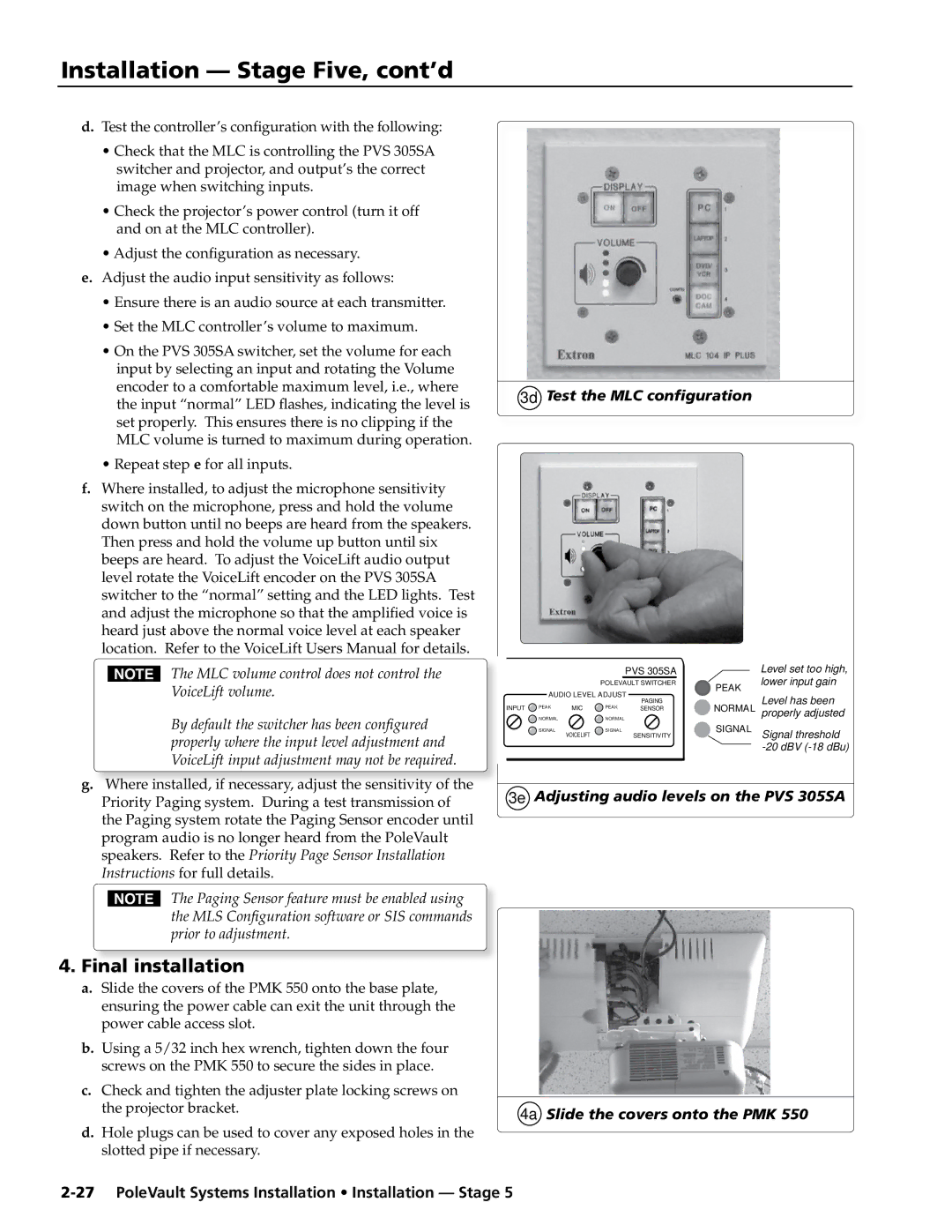
•On the PVS 305SA switcher, set the volume for each input by selecting an input and rotating the Volume encoder to a comfortable maximum level, i.e., where the input “normal” LED flashes, indicating the level is set properly. This ensures there is no clipping if the MLC volume is turned to maximum during operation.
•Repeat step e for all inputs.
f.Where installed, to adjust the microphone sensitivity switch on the microphone, press and hold the volume down button until no beeps are heard from the speakers. Then press and hold the volume up button until six beeps are heard. To adjust the VoiceLift audio output level rotate the VoiceLift encoder on the PVS 305SA switcher to the “normal” setting and the LED lights. Test and adjust the microphone so that the amplified voice is heard just above the normal voice level at each speaker location. Refer to the VoiceLift Users Manual for details.
NThe MLC volume control does not control the VoiceLift volume.
By default the switcher has been configured properly where the input level adjustment and VoiceLift input adjustment may not be required.
g.Where installed, if necessary, adjust the sensitivity of the
Priority Paging system. During a test transmission of the Paging system rotate the Paging Sensor encoder until program audio is no longer heard from the PoleVault speakers. Refer to the Priority Page Sensor Installation Instructions for full details.
NThe Paging Sensor feature must be enabled using the MLS Configuration software or SIS commands prior to adjustment.
4.Final installation
a.Slide the covers of the PMK 550 onto the base plate, ensuring the power cable can exit the unit through the power cable access slot.
b.Using a 5/32 inch hex wrench, tighten down the four screws on the PMK 550 to secure the sides in place.
c.Check and tighten the adjuster plate locking screws on the projector bracket.
d.Hole plugs can be used to cover any exposed holes in the slotted pipe if necessary.
3d Test the MLC configuration
|
|
| PVS 305SA |
| Level set too high, |
|
| POLEVAULT SWITCHER | PEAK | lower input gain | |
AUDIO LEVEL ADJUST |
| ||||
| Level has been | ||||
INPUT PEAK | MIC | PEAK | PAGING | NORMAL | |
SENSOR | properly adjusted | ||||
NORMAL |
| NORMAL |
| ||
|
|
|
| ||
SIGNAL | VOICELIFT | SIGNAL | SENSITIVITY | SIGNAL | Signal threshold |
|
|
|
|
| |
3e Adjusting audio levels on the PVS 305SA
4a Slide the covers onto the PMK 550