PoleVault Systems
Installation Guide
Safety Instructions English
Precautions
Consignes de Sécurité Français
Sicherheitsanleitungen Deutsch
Introduction
PoleVault Systems Installation Introduction
FCC Class B Notice
Introduction, contd
PoleVault System installation and wiring overview
PoleVault Systems Installation Introduction Planning
Typical classroom installation
Room layout
Room
Introduction Planning, cont’d
Example classroom installation
Location of the screen and projector
ADA overhead and side clearance requirements
Location of MediaLink Controller and Wall Plates
Example classroom with four speaker installation
Location of source devices
Cabling obstacles
Inventory
Introduction Inventory Overview
Included items
PoleVault System Devices and Hardware, cont’d
Introduction Inventory Overview, cont’d
Optional installation hardware
Items not included
Installation tools
Outline of installation steps
Installation Overview
PoleVault Systems Installation Installation
PoleVault Systems Installation Installation Stage
Stage One Install the Screen and Projector
PCM 340 Projector Drop Ceiling Mount
Slotted Pipe Supplied with PCM
Install projector to verify location
Installation Stage One, cont’d
Mark screen location
1a Mark the screen location
Verify the image location
2f Slide and lock the projector onto the adjuster plate
2e Attach the bracket to the projector
Horizontal offset
5a Mark structural ceiling for lag eye bolt installation
Preliminary safety hardware installation
Cut the ceiling tile
4b Take measurements with the PCM 340 on the T-frame
Secure the Projector Drop Ceiling Mount to the ceiling
Finish Projector Drop Ceiling Mount installation
7a Attach turnbuckles at the corners
7c Hand tighten the turnbuckles
Install the Screen
Install the electrical box if required
8a Install Raco box and plaster ring
This stage involves installing the devices shown below
Stage Two Install the Wall Plates and MLC 104 IP Plus
MLC 104 IP Plus MediaLink Controller
Cables
Installation Stage Two, cont’d
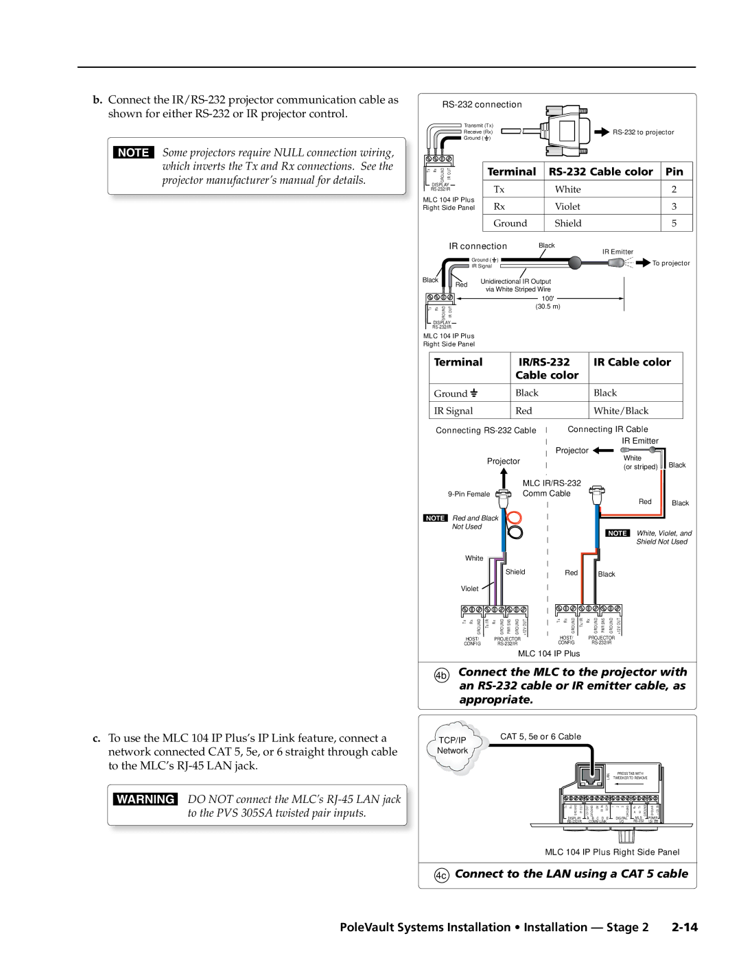
IR/RS-232 communications cable control cable
RS-232 or to an IR emitter
1d Features for mud ring installation
Install the mud rings
MLC 104 IP Plus mud ring
1c Insert the mud ring
Pull the cables at the input locations
Signal Cable Label color
2c Pull the cables at each location
MLC 104 IP Plus controller
Install wall plates
Wire stripping lengths
Install MediaLink Controller
4a Connecting the MLC to the switcher
Connect the MLC to the projector with
4c Connect to the LAN using a CAT 5 cable
An RS-232 cable or IR emitter cable, as
Appropriate
4e Secure the MLC 104 IP Plus to the mud ring
Connections made to the MLC 104 IP Plus
FF 120 Flat Field Ceiling Speakers
Stage Three Install the FF 120 Ceiling Speakers
Install the speaker on the drop ceiling
Installation Stage Three, cont’d
2h Attach safety cable
Cut ceiling tile
Pole captive screw connector
Terminate the speaker cable for the PVS switcher
Stereo or dual mono output using parallel speaker wiring
To terminate the cable, strip the end of the cable 0.2 inch
This stage covers installing the devices shown below
Stage Four Install the PMK 550 and the PVS 305SA
PVS 305SA PoleVault Switcher
PMK 550 Pole Mount Kit
PoleVault Systems Installation Installation Stage 4
Install the PMK 550 base plate
Pull the cables at the switcher location
Installation Stage Four, cont’d
Switcher and projector cable overview
2b Gather the cables, pass them down the pipe
BControl/power cable from the MLC 104 IP Plus
Finish installing the Pole Mount kit
4a Connect the cables to the switcher
Connect the cables as follows to the PVS 305SA
4d Cable the projector
4b Reattach UPB bracket and 4c projector
Configure the switcher MLS Switcher Configuration program
Stage Five Configure the Switcher and the System
Global configurator software
Configure the system Global Configurator
Installation Stage Five, cont’d
3c Check that an image is present, adjust as needed
Loosen all pivot screws and adjust the vertical angle
Test the system
Adjust the configuration as necessary
Final installation
Where installed, if necessary, adjust the sensitivity
3d Test the MLC configuration
Align the arrows on the housing rim and the dome tab
Optional Accessory Installation VoiceLift System
Attach the Z bracket to the ceiling tile and the back plate
Plug VoiceLift cable into PVS 305SA
Open the sensor and loop a wire around the sensor
Optional Accessory Installation Priority Page Sensor Kit
Priority Page Sensor Kit included parts
UL-compliant junction box and cover
Typical paging system with the PVS 305SA switcher
Testing and Adjustment Procedure
4 Sensitivity knob adjustment
Reference Information
PoleVault Systems Installation Reference Information
Lbs 0.1 kg
Wall or furniture mountable with included Decora wall plate
Extron PCM
Reference Information, cont’d
PVS 305SA specific symbol definitions
SIS Commands
SIS Command/Response Table Ascii Telnet
PoleVault Systems Installation Basic SIS Commands
Extron USA West