Theory of Operation 4

Detailed Circuit Description

High Voltage Supply Section

4-17.

The high voltage supply allows normal operation from a pair of nominal 400V dc supplies, or troubleshooting operation in a reduced voltage mode with a pair of nominal 50V dc supplies. Switching between normal and reduced-voltage operation is done by removing the plug from J301 and inserting it into J303. See Section 7 for the procedure to do this. (Plug P301 is wired with both 400V and 50V transformer taps so that the 400V taps are connected in the circuit when P301 is plugged into J301, and the 50V taps are connected in the circuit when P301 is plugged into J303.)

Two sets of high voltage rectifiers, CR301 through CR304 and CR310 through CR313, form bridge rectifiers for the positive and negative supplies, respectively. The output from these bridges is filtered by C301/C321 and C320/C322. The capacitor pairs are configured in series to obtain the necessary working voltage. Bleeder resistors R303, R314, R315, and R 308 discharge C301/C321 when power is removed and form a voltage divider that equalizes the voltage across halves of C301. Resistors R335, R337, R336, and R339 do the same function for C302/C322.

Warning

Do not rely on the power supply LEDs as an indication of the presence of high voltage. Always use a voltmeter to check for high voltage between TP307 and TP301, and between TP307 and TP304.

Components CR317 and CR318 are high intensity red LEDs that provide visual indication of the presence of high voltage. These LEDs have high luminosity at low current levels. They are located in series with the bleeders for the positive and negative supplies, using about 1 mA of current for bias. Under average lighting conditions, these LEDs are visibly lit with as little as 40V on C301/C321 and C320/C322. Zeners VR306 and VR307 are normally off, as their zener voltages are greater than the forward voltage of the LEDs. However, should an LED fail, these zeners carry enough current to allow the bleeder resistors to function.

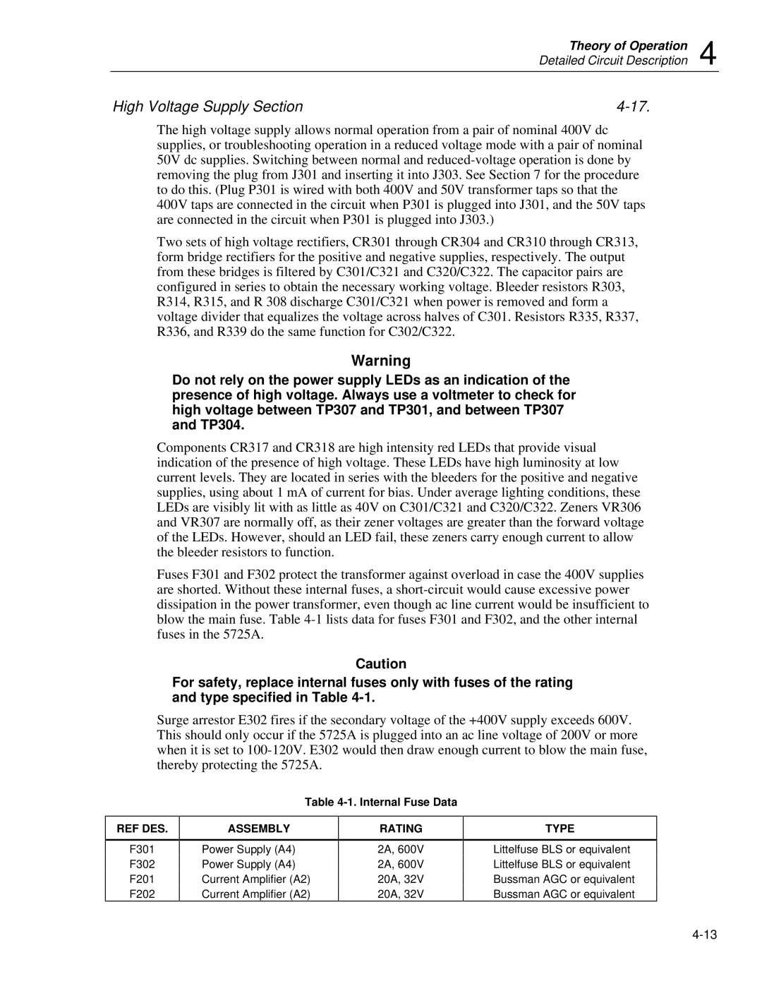
Fuses F301 and F302 protect the transformer against overload in case the 400V supplies are shorted. Without these internal fuses, a short-circuit would cause excessive power dissipation in the power transformer, even though ac line current would be insufficient to blow the main fuse. Table 4-1 lists data for fuses F301 and F302, and the other internal fuses in the 5725A.

Caution

For safety, replace internal fuses only with fuses of the rating and type specified in Table 4-1.

Surge arrestor E302 fires if the secondary voltage of the +400V supply exceeds 600V. This should only occur if the 5725A is plugged into an ac line voltage of 200V or more when it is set to 100-120V. E302 would then draw enough current to blow the main fuse, thereby protecting the 5725A.

REF DES.

F301

F302

F201

F202

Table 4-1. Internal Fuse Data

ASSEMBLY

RATING


Power Supply (A4)

2A, 600V

Power Supply (A4)

2A, 600V

Current Amplifier (A2)

20A, 32V

Current Amplifier (A2)

20A, 32V

TYPE

Littelfuse BLS or equivalent Littelfuse BLS or equivalent Bussman AGC or equivalent Bussman AGC or equivalent

4-13

Page 71
Image 71
Fluke 5725A instruction manual High Voltage Supply Section, Internal Fuse Data

5725A specifications

The Fluke 5725A is a high-performance, multifunctional temperature calibration source designed to meet the demanding requirements of laboratory and industrial environments. Renowned for its accuracy, reliability, and versatility, the 5725A serves as a powerful tool for engineers and technicians engaged in temperature calibration processes.

At the core of the 5725A is its advanced measurement technology, which allows for precision temperature calibrations across a wide range. With an operating temperature range from -200°C to 660°C, it caters to various applications, making it suitable for calibrating thermocouples, resistance temperature detectors (RTDs), and other temperature measurement devices.

One of the standout features of the Fluke 5725A is its outstanding accuracy, boasting a specified uncertainty of just ±0.15°C. This level of precision ensures that users can maintain compliance with regulatory standards and regulatory requirements in fields such as aerospace, pharmaceuticals, and manufacturing.

The Fluke 5725A is equipped with dual-channel capabilities, allowing users to calibrate two devices simultaneously. This enhances productivity by minimizing downtime and optimizing workflow efficiency. The intuitive touchscreen interface simplifies operations, enabling users to view measurements, set up test parameters, and access historical data with ease.

Versatile connectivity options such as USB and Ethernet enable seamless integration into existing systems and allow for data transfer, remote control, and configuration. This feature empowers technicians to conduct calibrations efficiently, whether on-site or remotely.

The robust design of the Fluke 5725A ensures its durability in demanding environments. Built with high-quality materials, it is resistant to shocks and vibrations, making it suitable for use in manufacturing plants and laboratories where equipment may be subjected to harsh conditions.

Another notable characteristic of the 5725A is its ability to generate stable temperature outputs with minimal drift, contributing to consistency in calibration results. Its built-in self-test functionality helps ensure that the unit remains in peak operating condition, giving users confidence in their calibration processes.

In summary, the Fluke 5725A is a top-tier temperature calibration source that excels in accuracy, reliability, and user-friendliness. Whether in laboratory settings or industrial applications, its advanced technologies and features make it an essential tool for professionals tasked with maintaining precision in temperature measurements.