MANUALUSER’S 24-wire dot matrix printers
User’s Manual
User’s Manual
Manufacturers Declaration of Conformity
Trademark Acknowledgment
User’s Manual
User’s Manual
Contents
10-1
Changing Head Gap Adjustment Options
12-1
11-1
IN-1
Image and graphics reproduction
Introduction
Package
Contents
Functions
Parts
Inside
Or continuous forms width
Lists the printer parts and functions
Recommended
Setting Up the Printer
Removing Stopper Cushion
Check that the jam removal lever is locked
Installing the Paper Guide
Insert the platen knob and align it with the gear teeth
Installing the Platen Knob
Plug the power cord into an outlet
Connecting the Power Cord
Connecting the Interface Cable
User’s Manual
Choosing a Cassette
Installing the Ribbon Cassette
Preparing the Ribbon Cassette
Installing the Ribbon Cassette
Close the top cover of the printer
Removing the Ribbon Cassette
Lift the reverse guide and remove the old ribbon
Replacing the Subcassette
Paper tape
Knob Lock tabs B
Turn on the printer power switch
Loading Paper
Loading Continuous Forms Front
Loading Continuous Forms Front
Tractor pins Paper holders Tractors Continuous forms
Close the front cover of the printer
Lower the cut-sheet tray
Indicator
Loading
Forms Rear Cutting
Forms
Turn on printer power
Raise the paper guide. See Installing the Paper Guide on
Loading Cut Sheets
Align the cut-sheet guide with the reference point
Open the front tray
Cut-sheet guide Cut sheet
Printing on Cut Sheets
Cut sheet Continuous forms
Returning to Continuous Forms
Online
Using
Operating the Printer
Control Panel
Locked
Friction
Front Tractor
Rear Tractor
Load
LF/FF
Font
Lock
Online + Tear OFF
Menu
Tear OFF
Paper Path
Friction *2
Power
Alarm
Online *2
Next Display
Online *1
Turning Printer Power On Off Test Printing
Test Printing
Test printing sample
Demonstration Pattern Printing
Demonstration pattern
Sensor Detection
User’s Manual
Clearing Paper Jams
Continuous Forms Front
Top cover Print head Paper thickness lever
Cut Sheets
Cut Sheets
User’s Manual
Shows the size range for continuous forms
Paper Specifications
Continuous Forms
Parts do not separate or
Become misaligned easily
Misaligned
Types of binding
Single-sided zigzag spot gluing Combination of the other two
30 mm
Printing
Area Size in mm Remarks
Type Number Ream weight in g/cm Front
Paste here FrontSide
Labels
Ambient temperature 40C
Or more
25.4
Formats
Recommended label formats
Label arrangement
Preprinting
Precautions
Leave an interval of 8 mm 0.3 in or greater
Unit mm
Miscellaneous
Overview
Setup Mode
Chapter Organization Activating Setup Mode
Initial setup mode printout
Mode
Using Setup
Using Setup Mode
Setup mode summary
Exit setup mode, saving the new font and spacing
Printing a List of Options
Default settings at shipment
MENU1 Emulate
Setting Required Options
Changing MENU1 MENU2 Options
DPL24C+
XL24E
ESC/P2
Draft
Quality
Letter
Report
CHAR-H
CHAR-W
Normal
Times
Condnsd
Attrib
None
Italics
TOP-MRG
Swedish
Languge
USA
German
ISO-LTN
ELOT928
PG-DHN
LATIN-P
Graphic
CHR-SET
SET
Italic
CR & LF
Enable
Disable
CR-CODE CR only
OVR-PRT
Rghtend Wrap
End-of-line wrap. Causes a carriage return plus a line
Feed
Change other MENU1 or MENU2 options as required
Select MENU1 or MENU2
ADJUST, or Config
Default does not reset options handled by Hardware
Hardware
Changing
2KBYTE2
WORD-LG
BIT
Buffer
REV-CHL
SPACE1
XON/XOF
DTR
Printer detects CD
Printer ignores CD
Changing Print Adjustment Options
Cutfine
CNT-ORG
Cntfine
CUT-ORG
Fcntadj
Rcntadj
CUT-ADJ
CNT-ORG
Tearpos Visible
Changing Configuration Options
Tearoff Manual
Auto
Loadtim
TEAR-EN SEC
Cutload Auto
Button
Tractor
Setup
ALL
CONT-PE
Tearoff Manual Auto
PLY POS.A POS.B POS.C POS.D Manual
Changing Head Gap Adjustment Options
Amount
PLY
Select SAVE&END
Resetting Default Values
Using Diagnostic Functions
Test printing SELF-TST
Hex dump printing HEX-DUMP
Sample hex dump
Checking vertical print alignment V-ALMNT
Bars offset to the left
Correct vertical printing alignment
You can also exit setup mode to exit V-ALMNT
Listed for IBM Proprinter XL24E and Epson ESC/P2 emulations
Setup Mode
Flowchart in -6 shows the setup mode for the Fujitsu
Reference
Hardwre Adjust Config GAP-ADJ
LF code
AGM
Performing Online Setup
Print head
Ribbon cassette
Correct continuous forms loading
User’s Manual
To troubleshoot printer problems, follow the flowchart
Troubleshooting
Troubleshooting
Inspection Maintenance
Daily Inspection and Maintenance
11-2
Specifications
Vertical ⋅
Configuration body Horizontal Face Draft Quality
Printer Specifications Printer specifications
Parallel two pins
Dimensions
D86B-1138-C359 for DL6600 Pro
Consumables and Options
Aptc
D86B-1138-C353 for DL6600 Pro
User’s Manual
Command Sets
Fujitsu DPL24C
Select underline type
Condensed characters off
DC2
ESC T
ESC P
Space Backspace Carriage return Elite 12 cpi
ESC M
Pica 10 cpi
255 ESC J n
Line feed Reverse line feed
ESC LF
Form feed
ESC O
Horizontal tab execution
255 ESC VT n
Set right margin 0 ≤ n ≤ ESC Q n
ESC =
Can
DC1
DC3
Resident font
ESC % m n
Select font m with source and style set by n
Bits 0 and 1 Font device selection
255 0 ≤ n2 ≤
Select character spacingn/360 inch, font attributes
Fixed 10 cpi 12 pt
ESC NUL m n
Bits 4 and 5 Specifies the quality of characters to be reg
Istered
Cut-Sheet Feeder Control
EAN
Codabar nw-7 EAN
Ignore the paper-out sensor
Enable paper-out sensor
Sound bell
BEL
LETTER, REPORT, Draft
Cour 10, Prstg 12, Comprsd
BOLDFCE, Pica 10, Corresp
Downld 0, Downld ESC %
ESC G ESC H
NONE, ITALICS, Condnsd
SHADOW, Bold
ESC E ESC F
LF-ONLY, LF & CR
DC1/DC3 ENABLE, Disable
NO-SLSH, Slash
CR-ONLY, CR & LF
DC4
Unchanged Normal Double Single M4 controls character width
Unchanged Normal Double
≤ t1 ≤ 255, 0 ≤ t2 ≤ 255, t3 = 0, t4 = 180 or
Space Backspace Carriage return Elite characters on
Set line spacing to 7/72 inch
Set line spacing to n/216 inch 0 ≤ n ≤ ESC 3 n
ESC B NUL
ESC D NUL
ESC Q #
ESC EM
ESC EM E
ESC EM R
Underline on or off ESC n On n = 1, off n =
ESC n 1 n
Select line
Line feed Form feed
Space Backspace Carriage return Set elite
Set pica
ESC c n1 n2
ESC D
127 ESC C n Set page length to n inches 1 ≤ n ≤ ESC C NUL n
255 0 ≤
ESC t n
Delete character
DEL
ESC % n
Print raster image graphics
ESC X m n 1 n
Point
ESC * m n 1 n 2 data
ESC @
Enter online setup mode ESC e Online data
User’s Manual
Parallel Interface
Interface Information
ACK
Dstb
Slct
Inprm
Data transfer, it is used as data bit
This signal is set low when the printer is
This signal is used to indicate that data is
Ready to send data to the host. During
Figure C-1 Data transmission timing
Data Transmission Timing
Figure C-2 Data transmission timing
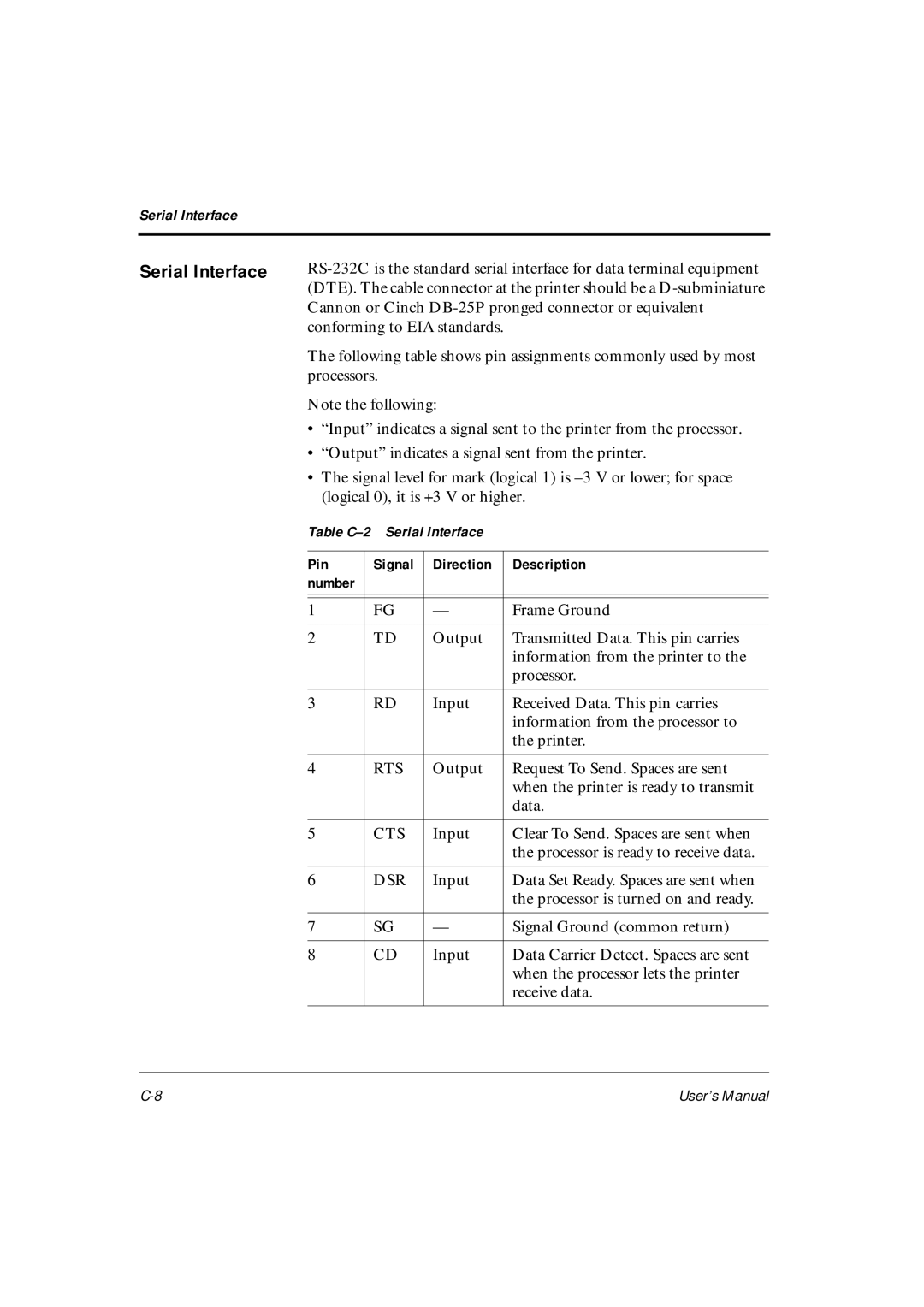
Serial Interface
RTS
CTS
ETX/ACK selectable
When the printer is turned on
Serial Options
Ready
TD RD
Cable Wiring
Figure C-1 Cable wiring DSR-enabled control
Serial Protocols
ON/XOFF
ETX/ACK
Basic character sets for DPL24C Plus and IBM XL24E emulation
Character Sets
User’s Manual
User’s Manual
User’s Manual
User’s Manual
User’s Manual
User’s Manual
LITHUA1 Lithuanian LITHUA2 Lithuanian
MIK
User’s Manual
User’s Manual
User’s Manual
User’s Manual
User’s Manual
Character Sets
Ecma ECMA94
USA*2
PG-MAC ELOT927
LATN2-T
LITHUA2 MIK
Macedon ABG ABY
User’s Manual
Using the LCD/LED Type Control Panel
Control panel components
LCD screen
Indicator lights
Unload
Buttons
Points to remember about basic menus
Menus and functions
Executes form feed
Changes the font, print quality, and pitch
Executes line feed
Backward. To invert the arrow, press the ↓↑ but- ton
Executing a form feed or line feed
Executing a micro line feed
To execute a form feed or line feed
To tear off continuous forms
Resetting the printer
To reset the printer
Tearing off continuous forms
Changing print font, quality, and pitch temporarily
Letter Report Draft
Selecting MENU1 or MENU2
Entering setup mode
Enabling or disabling lock mode
Exiting setup mode
Selecting options
Using the Setup Menus
Selections are not in effect until they are saved
Starting functions
Example of operations
Save Exit from Setup SELF-TEST Alignment
Saving changed options
Selecting options in MENU1 and MENU2
Using the Save function
Exit from Setup
Press F1 until SELF-TEST appears under Func
Printing the self-test
Correcting vertical character displacement
Power-on Special Functions
Exit
Messages
Stop
USE Save
Appears for 2 seconds immediately
Where line 001 is the top-of-form
Where xxxx is -128 to +127
Internal test Printer is performing its
Exit Stop GO
Speed Incr Decr
MICRO↑ Exit Save
Operational error messages
Messages indicating user-correctable problems
LCD model
Cover open Cover is open Shut the cover Error
Table E-5 Warning errors list
Table E-5 Warning errors list
Buffer overflow
Or check the interface cable
Table E-6 lists nonfatal error messages alphabetically
Space for download data, or check the format
Download data
Compress
Messages indicating fatal errors
Cour
Prestg
Fatal
Index
Index
Platen Platen knob
IN-4
IN-5
IN-6
Fujitsu Offices
C147-E041-05EN