4.6.4Time base generator circuit
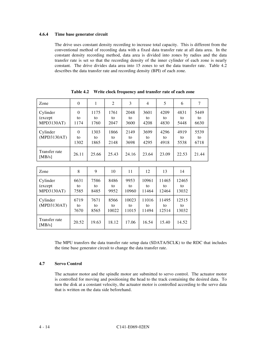
The drive uses constant density recording to increase total capacity. This is different from the conventional method of recording data with a fixed data transfer rate at all data area. In the constant density recording method, data area is divided into zones by radius and the data transfer rate is set so that the recording density of the inner cylinder of each zone is nearly constant. The drive divides data area into 15 zones to set the data transfer rate. Table 4.2 describes the data transfer rate and recording density (BPI) of each zone.
Table 4.2 Write clock frequency and transfer rate of each zone
Zone | 0 | 1 | 2 | 3 | 4 | 5 | 6 | 7 | |
|
|
|
|
|
|
|
|
| |
Cylinder | 0 | 1175 | 1761 | 2048 | 3601 | 4209 | 4831 | 5449 | |
(except | to | to | to | to | to | to | to | to | |
MPD3130AT) | 1174 | 1760 | 2047 | 3600 | 4208 | 4830 | 5448 | 6630 | |
|
|
|
|
|
|
|
|
| |
Cylinder | 0 | 1303 | 1866 | 2149 | 3699 | 4296 | 4919 | 5539 | |
(MPD3130AT) | to | to | to | to | to | to | to | to | |
| 1302 | 1865 | 2148 | 3698 | 4295 | 4918 | 5538 | 6718 | |
|
|
|
|
|
|
|
|
| |
Transfer rate | 26.11 | 25.66 | 25.43 | 24.16 | 23.64 | 23.09 | 22.53 | 21.44 | |
[MB/s] | |||||||||
|
|
|
|
|
|
|
| ||
|
|
|
|
|
|
|
|
| |
|
|
|
|
|
|
|
|
| |
Zone | 8 | 9 | 10 | 11 | 12 | 13 | 14 |
| |
|
|
|
|
|
|
|
|
| |
Cylinder | 6631 | 7586 | 8486 | 9953 | 10961 | 11465 | 12465 |
| |
(except | to | to | to | to | to | to | to |
| |
MPD3130AT) | 7585 | 8485 | 9952 | 10960 | 11464 | 12464 | 13032 |
| |
|
|
|
|
|
|
|
|
| |
Cylinder | 6719 | 7671 | 8566 | 10023 | 11016 | 11495 | 12515 |
| |
(MPD3130AT) | to | to | to | to | to | to | to |
| |
| 7670 | 8565 | 10022 | 11015 | 11494 | 12514 | 13032 |
| |
|
|
|
|
|
|
|
|
| |
Transfer rate | 20.52 | 19.63 | 18.12 | 17.06 | 16.54 | 15.40 | 14.52 |
| |
[MB/s] |
| ||||||||
|
|
|
|
|
|
|
| ||
|
|
|
|
|
|
|
|
|
The MPU transfers the data transfer rate setup data (SDATA/SCLK) to the RDC that includes the time base generator circuit to change the data transfer rate.
4.7Servo Control
The actuator motor and the spindle motor are submitted to servo control. The actuator motor is controlled for moving and positioning the head to the track containing the desired data. To turn the disk at a constant velocity, the actuator motor is controlled according to the servo data that is written on the data side beforehand.
4 - 14 |
|