5.6.4Power-on and reset
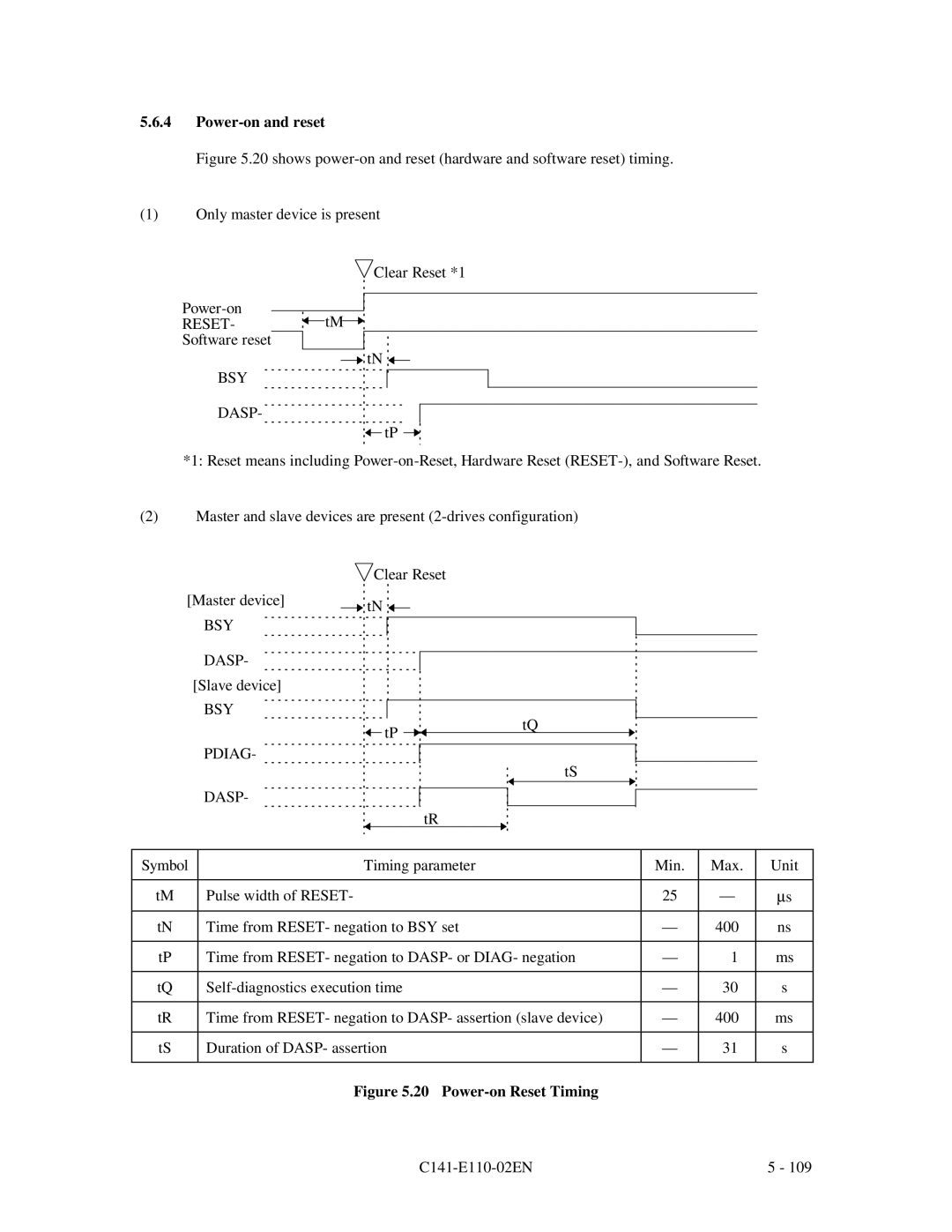
Figure 5.20 shows power-on and reset (hardware and software reset) timing.
(1)Only master device is present
 Clear Reset *1
Power-on
RESET- tM
tM

Software reset
![]()
![]() tN
tN ![]()
![]()
BSY
DASP-
![]()
![]() tP
tP
*1: Reset means including
(2)Master and slave devices are present
![]() Clear Reset
Clear Reset
[Master device] |
| tN |
|
|
|
|
|
|
|
|
|
|
|
|
|
| |||||
|
| BSY |
|
|
|
|
|
|
|
|
|
|
|
|
|
| |||||
|
|
|
|
|
|
|
|
|
|
|
|
|
|
|
|
|
|
|
| ||
|
|
|
|
|
|
|
|
|
|
|
|
|
|
|
|
|
|
| |||
|
| DASP- |
|
|
|
|
|
|
|
|
|
|
|
|
|
|
|
|
|
| |
|
|
|
|
|
|
|
|
|
|
|
|
|
|
|
|
|
|
|
| ||
| [Slave device] |
|
|
|
|
|
|
|
|
|
|
|
|
|
|
|
|
|
| ||
|
| BSY |
|
|
|
|
|
|
|
|
|
|
|
|
|
|
|
|
|
| |
|
|
|
|
|
|
|
|
|
|
|
|
|
| tQ |
|
|
|
| |||
|
| PDIAG- |
|
| tP |
|
|
|
|
|
|
|
|
|
|
| |||||
|
|
|
|
|
|
|
|
|
|
|
|
|
|
|
| ||||||
|
|
|
|
|
|
|
|
|
|
|
|
|
|
|
|
|
|
|
| ||
|
|
|
|
|
|
|
|
|
|
|
|
|
|
|
|
|
|
|
| ||
|
|
|
|
|
|
|
|
|
|
|
|
|
|
|
| tS |
|
|
|
| |
|
| DASP- |
|
|
|
|
|
|
|
|
|
|
|
|
|
|
|
|
|
| |
|
|
|
|
|
|
|
|
|
|
|
|
|
|
|
|
|
|
|
| ||
|
|
|
|
|
|
|
|
|
|
|
| tR |
|
|
|
|
|
|
|
| |
|
|
|
|
|
|
|
|
|
|
|
| ||||||||||
Symbol |
|
|
| Timing parameter |
|
|
|
| Min. | Max. | Unit | ||||||||||
|
|
|
|
|
|
|
|
|
|
|
|
|
|
|
|
|
|
|
|
| |
tM |
| Pulse width of RESET- |
|
|
|
|
|
|
|
|
|
|
|
|
|
|
| 25 | — | μs | |
|
|
|
|
|
|
|
|
|
| ||||||||||||
tN |
| Time from RESET- negation to BSY set |
|
|
|
| — | 400 | ns | ||||||||||||
|
|
|
|
|
|
| |||||||||||||||
tP |
| Time from RESET- negation to DASP- or DIAG- negation |
| — | 1 | ms | |||||||||||||||
|
|
|
|
|
|
|
|
|
| ||||||||||||
tQ |
|
|
|
|
| — | 30 | s | |||||||||||||
|
|
|
|
|
|
| |||||||||||||||
tR |
| Time from RESET- negation to DASP- assertion (slave device) |
| — | 400 | ms | |||||||||||||||
|
|
|
|
|
|
|
|
|
| ||||||||||||
tS |
| Duration of DASP- assertion |
|
|
|
| — | 31 | s | ||||||||||||
|
|
|
|
|
|
|
|
|
|
|
|
|
|
|
|
|
|
|
|
|
|
Figure 5.20 Power-on Reset Timing
| 5 - 109 |
