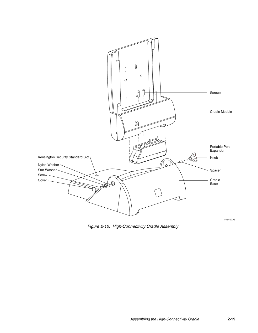
Manuals
/
Brands
/
Computer Equipment
/
Network Card
/
Fujitsu Siemens Computers
/
Computer Equipment
/
Network Card
Fujitsu Siemens Computers
Point 1600, Point 500
Figure 2-10. High-Connectivity Cradle Assembly
1
31
52
52
Download
52 pages, 499.61 Kb
Assembling the High-Connectivity Cradle
2-15
Figure 2-10. High-Connectivity Cradle Assembly
Cradle
Base
545HUCAS
Cover
Screw
Nylon Washer
Spacer
Knob
Portable Port
Kensington Security Standard Slot
Screws
Cradle Module
Star Washer
Expander
Contents
Main
Page
Page
Page
Agency Compliance
FCC Notice
Canadian DOC Compliance
Page
Tabl e of Contents
Page
About This Guide
Organization 0
Page
Chapter 1 Introduction to Connectivity Peripherals
Table 1-1. Connectivity Peripheral Model Numbers
Page
Cradle Module 1
The Portable Port Expander 1
Port Replicator 1
High-Usage C radle 1
High-Connectivity Cradle 1
Wall-Mount Cradle 1
Charge-Only Cradle 1
Chapter 2 Assembling and Installing Connectivity Peripherals
Portable Port Expander 2
Figure 2-1. Portable Port Expander Latch
Removing the Latch and Spacer (For In stallation in Cradle Module Onl y) 2
Latch Detail:
Figure 2-2. Bottom View, Portable Port Expander
Peripheral connectors on the portable port expander are described in Table 2-1.
Table 2-1. Portable Port Expander Connectors
Assemblin g th e Port Replicator 2
Figure 2-3. Installing the Portable Port Exp an der
Attaching the Feet 2
Attaching the Wire Catch 2
Figure 2-4. Port Replicator (Back View)
Figure 2-5. Bottom View, Port Replicator
Connectors on the port replicator are described in Table 2-2.
Table 2-2. Port Replicator Connectors
Using the Folding Desk Stand 2
Figure 2-6. Folding Desk Stand
Assemblin g th e H i gh - U s age C radle 2
Figure 2-7. High-Usage Cradle Assembly
Figure 2-8. High-Usage Cradle Bottom View
Table 2-3. High-Usage Cradle Connectors
Installing the High-Usage Cradle 2
Figure 2-9. Fastening Cradle Module to Desktop
Assembling the High-Connectivity Cradle 2
Figure 2-10. High-Connectivity Cradle Assembly
Assembling the High-Connectivity Cradle
2-15
Figure 2-11. High-Connectivity Cradle Bottom View
Installing the High-Connectivity Cradle 2
Table 2-4. High-Connectivity Cradle Connectors
Installing the Wall-Mount Cradle 2
Required Tools and Hardware 2
Page
Figure 2-12. Wall-Mount Cradle Mounting Plate
Figure 2-13. Coiling DC Suppl y Cable
Figure 2-14. Installing an FMWKB3 Keyboard
Figure 2-15. Wall-Mount Cradle Exploded View
Figure 2-16. Attaching Keyboard Tray Assembly to Mounting Plate (Right Side)
Page
Page
Figure 2-21. Checking Cradle Module Alignment
Testing the Wall-Mount Cradle After Installation 2
Figure 2-22. Wall-Mount Cradle Closed Position
Installing the Wall-Mount Cradle
Connectors on the wall-mount cradle are described in Table 2 -5.
Table 2-5. Wall-Mount Cradle Connectors
Installing the Charge-Only Cradle 2
Figure 2-23. Charge-Only Cradle
Confirming External Power Is Supplied 2
Figure 2-24. Status Lights on the Pen Tablet
MIC
Page
Index
C
H
K
M