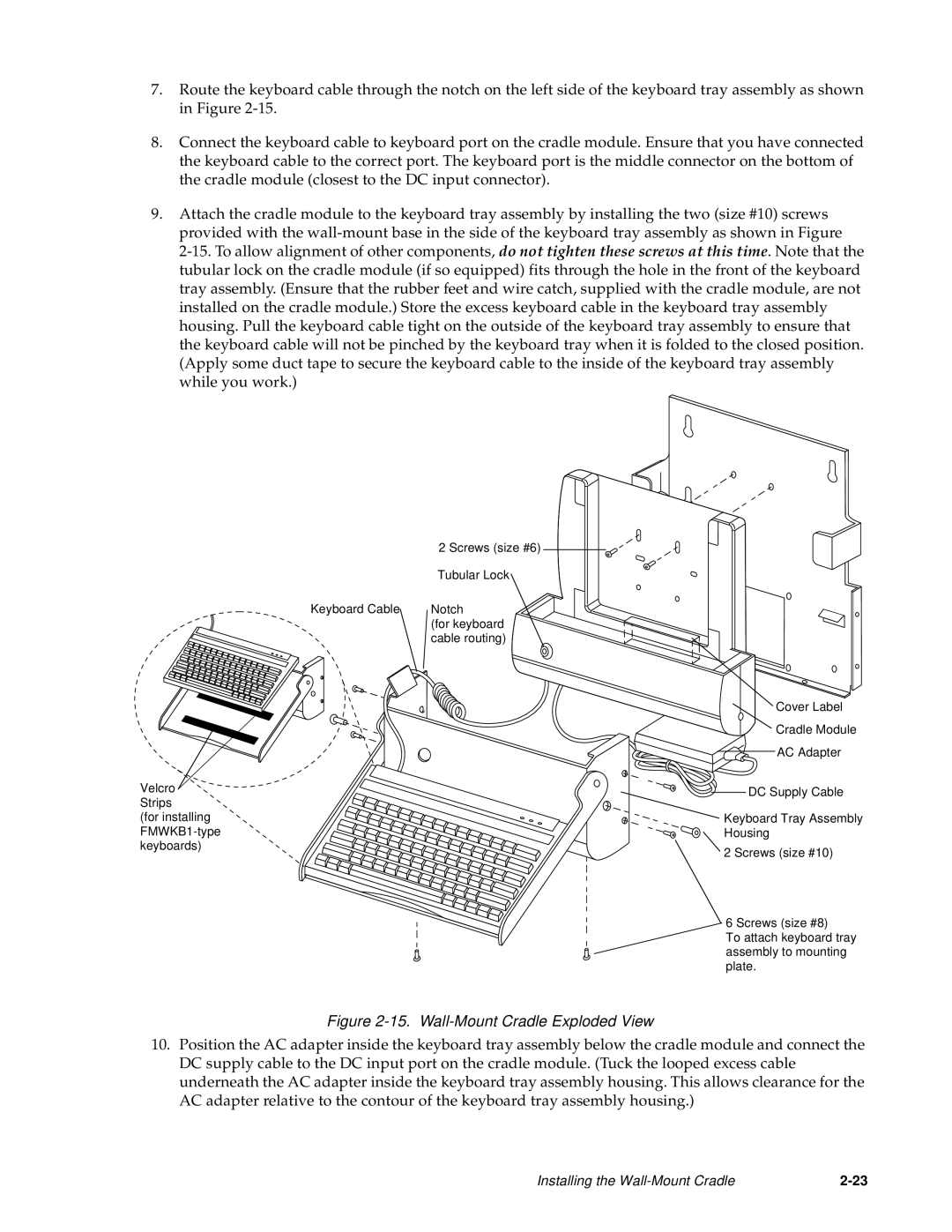
7.Route the keyboard cable through the notch on the left side of the keyboard tray assembly as shown in Figure
8.Connect the keyboard cable to keyboard port on the cradle module. Ensure that you have connected the keyboard cable to the correct port. The keyboard port is the middle connector on the bottom of the cradle module (closest to the DC input connector).
9.Attach the cradle module to the keyboard tray assembly by installing the two (size #10) screws provided with the
2 Screws (size #6) 
![]()
| Tubular Lock |
Keyboard Cable | Notch |
| (for keyboard |
| cable routing) |
Velcro![]()
Strips
(for installing
![]() Cover Label
Cover Label
![]() Cradle Module
Cradle Module
AC Adapter
DC Supply Cable
![]() Keyboard Tray Assembly
Keyboard Tray Assembly
Housing
![]() 2 Screws (size #10)
2 Screws (size #10)
![]() 6 Screws (size #8)
6 Screws (size #8)
To attach keyboard tray assembly to mounting plate.
Figure 2-15. Wall-Mount Cradle Exploded View
10.Position the AC adapter inside the keyboard tray assembly below the cradle module and connect the DC supply cable to the DC input port on the cradle module. (Tuck the looped excess cable underneath the AC adapter inside the keyboard tray assembly housing. This allows clearance for the AC adapter relative to the contour of the keyboard tray assembly housing.)
Installing the |