Quick Setup Guide
Accessories Supplied
Laser Safety
Precautions
Power Supply
Before you start
Connection to Power
Installation Location
Avoid the Hazards of Electrical Shock and Fire
Moisture Condensation Warning
Maintenance
Cleaning the Unit
About Copyright
Table of contents
Recording
Features
Playback
Editing
Symbol Description
Button names described
There may be a disc which cannot be used or played back
Front panel
Functional overview
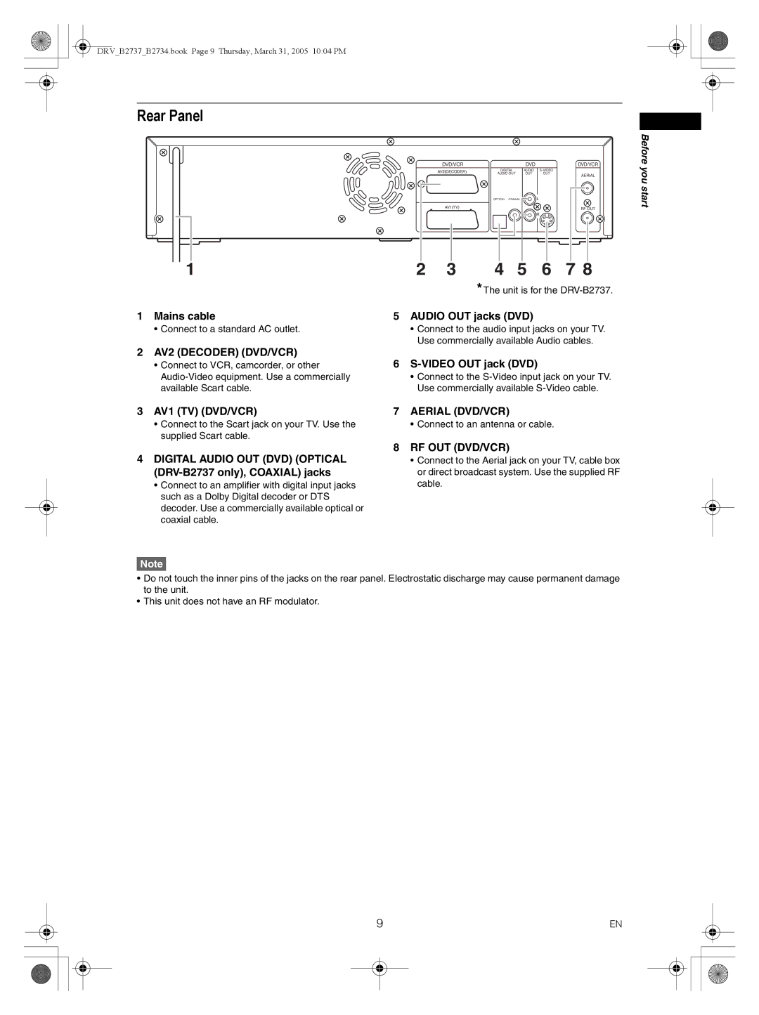
Mains cable Audio OUT jacks DVD
Rear Panel
Video OUT jack DVD
Digital Audio OUT DVD Optical DRV-B2737 only, Coaxial jacks
Remote Control
Setup button DVD / VCR
Timer PROG. button DVD / VCR
Repeat button DVD
Clear button DVD / VCR
VCR / DVD recorder Switching
Installing batteries in the remote control
About the remote control
VCR Select DVD DVD Select indicator VCR Select indicator
Easy Setting Menu
Setting menus
Guide to On Screen Displays
Display menu
Advanced Setting Menu
Display messages
Front Panel Display Guide
Connecting to external equipment
Connecting to a TV
Getting Started
Connections
Digital audio for better sound quality only for DVD
Connecting to an MD deck or DAT deck
After you have completed connections
Connections illustrated above are optional for better sound
Auto tuning
Channel setting
Manual tuning
Press Setup to exit
After completion, press Setup to exit
To skip a Preset channel
To select a channel
Move
Setting the clock
Auto Clock Setting
Manual Clock Setting
If you have a standard TV
Selecting the TV aspect ratio
Information on DVD recording
Recording
Type of discs
Recording speed
Information on copy control
Features
Making discs playable in other DVD players Finalise
Usable discs
Formatting a disc
Setting Auto Chapter
Choosing the recording format of a blank DVD-RW disc
You cannot set or clear chapter markers on DVD-R discs. See
Setting External input audio
Selecting the Sound mode
Insert a recordable disc Stop mode, press Setup
Reformatting a disc manually
Basic recording
Setting Bilingual Recording Audio
Turn on the unit and insert a recordable disc
Press DVD
Checking the recording picture and sound quality
One-touch timer recording OTR
Press REC Monitor again to exit
030 Normal Recording 800
Enter the date using Cursor U / D, then press Cursor P
Timer recording
Timer Programming list will appear
1st January
Press T-SET
To exit, press Setup or Timer Prog
Check the information on the list you will need
If PDC is on
If the timer programming did not complete correctly
To stop the timer recording in progress
Hints for timer recording
PDC Programme Delivery Control
If the starting time is same
Priority of overlapped settings
If the recording time is partially overlapped
If the recording time entirely overlaps
Settings for external equipment
Connection to external equipment
Recording from external equipment
Select VCR→DVD using Cursor U / D, then press Enter
Dubbing Mode
Press Setup to exit the setting menu Press DVD
Select DVD→VCR using Cursor U / D, then press Enter
To cancel the disc protect
Setting a disc to protect
Finalising discs
DVD to VCR duplication will start
Finalising is complete
Auto finalise
Information on playing back DVDs
Playing back discs
Playing back a DVD-RW / DVD-R / DVD+RW / DVD+R disc
Basic playback
Playing back a DVD-V / CD / Video CD
Playing back an MP3 / Jpeg
Kodak Picture CD
Playing back discs using the disc menu
Press DVD first
Press Stop S to stop playback
Playing back a disc using the title menu
Cancelling and Recalling the PBC function
Playing back a Video CD using the title menu
Insert a Video CD Stop mode, press Setup
PBC function for Video CDs
Special playback
Marker Setup
Slow forward / Slow reverse playback
Zoom
Title / Chapter search
Search
Searching for a Title
Searching for a Chapter
Direct Search
Track search
Repeat playback
Repeat / Random / Program playback / Slide Show
Random playback
Program playback
Switching audio soundtrack
Switching subtitles
Select the icon using Cursor L / P, then press Enter
Selecting the format of audio and video
Switching camera angles
Angle will switch each time you press Enter
Reducing block noise
Editing
Editing discs in Video mode
Disc editing
Guide to a title list
Press Setup
Guide to editing title names
Editing titles
Then press Enter
Setting or clearing chapter markers
Original Editing Original titles in VR mode
Editing discs in VR mode
Original Deleting titles
Editing original titles Original
Original Protecting titles
To protect a whole disc DVD-RW VR mode only
Original Releasing titles from protecting
Key icon will disappear from the title in the original list
Select Yes using Cursor U / D
Playlist Editing the Playlist in VR mode
Playlist Deleting titles
Playlist Deleting parts of titles Scene Delete
Playlist Editing titles
Playlist Setting or clearing chapter markers
Adding a chapter marker
Deleting a chapter marker
Playlist Setting pictures as thumbnails
Playlist Dividing a title
Playlist Combining titles
Playlist Deleting a Playlist
Playlist Adding titles to a Playlist
Playlist can be deleted if it is no longer needed
Playlist is deleted
Tour of the Setting menu
Changing the Setting menu
Disc Menu Language Default English
Language setting
Audio Language Default Original
Subtitle Language Default OFF
Audio setting
Display setting
FL Dimmer Default Bright
Screen Saver Default 10 minutes
Fast Forward with Audio Default OFF
Dynamic Range Control Default on
Dolby Digital conversion Default Stream
Settings for Mpeg Default PCM
Enter the current password using the Number buttons
Parental Lock Default All
Password is not yet set
Password is already set
Changing Video Out system
Setting TV system
VCR functions
Recording and one-touch timer recording OTR
Playback
Basic Recording
Index search
One-touch timer recording
Time search
Accidental erasure prevention
Mode Audio output Display on
Other operations
Hi-Fi Stereo Sound System
Symptom Remedy
Troubleshooting
Others
DVD VCR
Open / Close / Eject O
DVD
Pressing REC / OTR
VCR
ALL
Error message Cause Solution
Language Code
Language code
Glossary
General
Specifications
Recording
Tuner
DRVB2737B2734.book Page 73 Thursday, March 31, 2005 1004 PM
DRVB2737B2734.book Page 74 Thursday, March 31, 2005 1004 PM
DRVB2737B2734.book Page 75 Thursday, March 31, 2005 1004 PM
EEC
Declaration of Conformity