RS232 Port 1
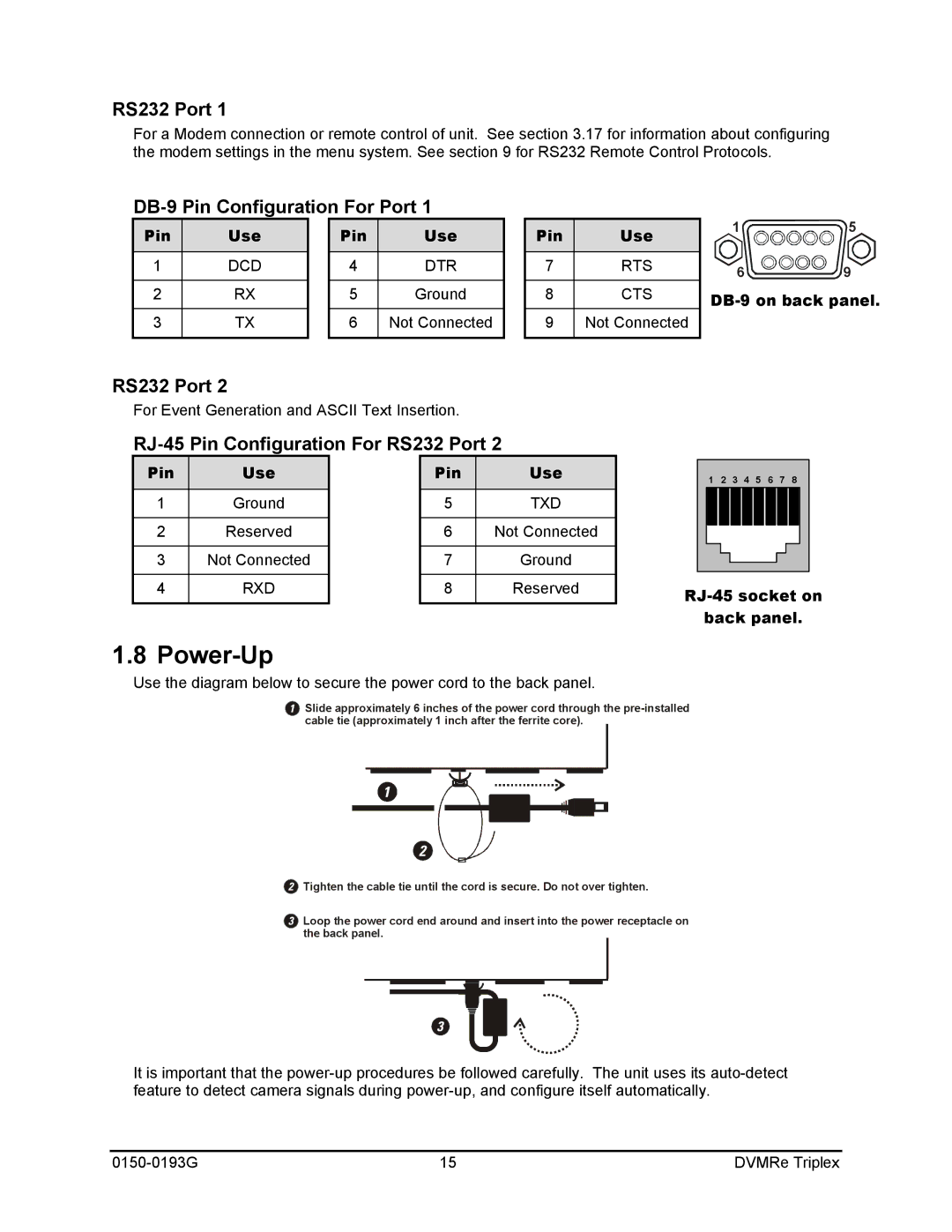
For a Modem connection or remote control of unit. See section 3.17 for information about configuring the modem settings in the menu system. See section 9 for RS232 Remote Control Protocols.
DB-9 Pin Configuration For Port 1
Pin | Use |
|
|
1DCD
2RX
3TX
Pin | Use |
|
|
4DTR
5Ground
6Not Connected
Pin | Use |
|
|
7RTS
8CTS
9Not Connected
1 ![]()
![]()
![]() 5
5
6 ![]()
![]() 9
9
DB-9 on back panel.
RS232 Port 2
For Event Generation and ASCII Text Insertion.
RJ-45 Pin Configuration For RS232 Port 2
| Pin |
|
| Use |
|
|
| Pin |
|
| Use |
|
|
|
|
|
|
|
|
|
|
|
|
|
|
|
|
|
|
|
|
|
|
|
| 1 2 3 4 5 6 7 8 |
|
| |||||||||||||
| 1 |
|
| Ground |
|
| 5 |
|
| TXD |
|
|
|
|
|
|
|
|
|
|
|
|
|
| |
|
|
|
|
|
|
|
|
|
|
|
|
|
|
|
|
|
|
|
|
|
|
|
|
| |
| 2 |
|
| Reserved |
|
| 6 |
|
| Not Connected |
|
|
|
|
|
|
|
|
|
|
|
|
|
| |
|
|
|
|
|
|
|
|
|
|
|
|
|
|
|
|
|
|
| |||||||
|
|
|
|
|
|
|
|
|
|
|
|
|
|
|
|
|
|
|
|
|
|
|
|
| |
| 3 |
|
| Not Connected |
|
| 7 |
|
| Ground |
|
|
|
|
|
|
|
|
|
|
|
|
|
| |
|
|
|
|
|
|
|
|
|
|
|
|
|
|
|
|
|
|
| |||||||
|
|
|
|
|
|
|
|
|
|
|
|
|
|
|
|
|
|
|
|
|
|
|
|
| |
|
|
|
|
|
|
|
|
|
|
|
|
|
|
|
|
|
|
|
|
|
|
|
|
|
|
| 4 |
|
| RXD |
|
| 8 |
|
| Reserved |
| ||||||||||||||
|
|
|
|
|
|
|
|
|
|
|
|
| |||||||||||||
|
|
|
|
|
|
|
|
|
|
|
|
|
| back panel. | |||||||||||
1.8 Power-Up
Use the diagram below to secure the power cord to the back panel.
1Slide approximately 6 inches of the power cord through the
1
2
2Tighten the cable tie until the cord is secure. Do not over tighten.
3Loop the power cord end around and insert into the power receptacle on the back panel.
3
It is important that the
15 | DVMRe Triplex |
