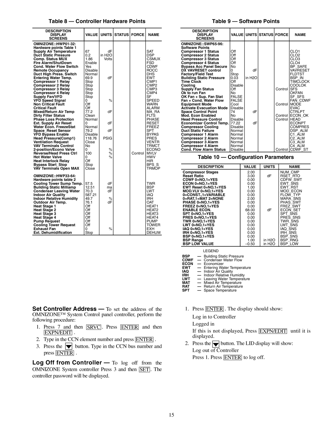
Table 8 — Controller Hardware Points

DESCRIPTION


DISPLAY

VALUE

UNITS

STATUS

FORCE

NAME

SCREENS


OMNIZONE::HWP01-32:


Hardware points Table 1


Supply Air Temperature

67

dF


SAT

Duct Static Pressure

0.2

in H2O


DSP

Comp. Status MUX

1.86

Volts


CSMUX

Fire Alarm/ShutDown

Enable


FSD

Cond. Water Flow Switch

Yes


CDWF

Remote Occupancy

Disable


ROCC

Duct High Press. Switch

Normal


DHS

Entering Water Temp.

69.9

dF


EWT

Compressor 1 Relay

Stop


CMP1

Compressor 2 Relay

Stop


CMP2

Compressor 3 Relay

Stop


CMP3

Compressor 4 Relay

Stop


CMP4

Supply Fan/VFD

Stop


SF

VFD Speed Signal

0

%


SPEED

Non Critical Fault

Off


WARN

Critical Fault

Off


ALARM

Mixed/Return Air Temp

77.2

dF


MA_RA

Dirty Filter Status

Clean


FLTS

Phase Loss Protection

Normal


PHASE

Ext. Supply Air Reset

0

dF


RESET

Water Econ. FreezeStat

Normal


FREEZ

Space_Reset Sensor

79.2

dF


SPT

VFD Bypass Enable

Disable


BYPAS

Head Pressure(Comp1)

118.76

PSIG


PRES

Ventilation Request

Close


VENTR

VAV Terminals Control

No


TRMCT

2-position/Econo Valve

0

%


ECONO

Reverse/Head Press Ctrl

100

%


Control

MVLV

Hot Water Valve

0

%


HWV

Heat Interlock Relay

Off


HIR

Bypass Start_Stop

Stop


BPS_S

VAV Terminals Open MAX

Close


TRMOP

OMNIZONE::HWP33-64:


Hardware points table 2


Cooling Tower Sump Temp.

57.5

dF


TWR

Building Static Milliamp

12.51

ma


BSP

Condenser Leaving Water

70.3

dF


LWT

Indoor Air Quality

587.21


IAQ

Indoor Relative Humidity

49.7

%


IRH

Outdoor Air Temp.

76.1

dF


OAT

Heat Stage 1

Off


HEAT1

Heat Stage 2

Off


HEAT2

Heat Stage 3

Off


HEAT3

Heat Stage 4

Off


HEAT4

Pump Request

Off


PUMP

Cooling Tower Request

Off


TOWER

Exhaust Fan

0

%


EXH

Ext. Dehumidification

Stop


DEHUM

Set Controller Address — To set the address of the OMNIZONE™ System Control panel controller, perform the following procedure:

1.Press 7 and then SRVC . Press ENTER and then EXPN/EDIT .

2.Type in the CCN element number and press ENTER .

3.Press the button. Type in the CCN bus number and press ENTER .

Log Off from Controller — To log off from the

OMNIZONE System controller Press 3 and then SET . The controller password will be displayed.

Table 9 — Software Points


DESCRIPTION


DISPLAY

VALUE

UNITS

STATUS

FORCE

NAME


SCREENS


OMNIZONE::SWP65-96:


Software Points


Compressor 1 Status

Off


CLO1


Compressor 2 Status

Off


CLO2


Compressor 3 Status

Off


CLO3


Compressor 4 Status

Off


CLO4


Bypass Acc Panel Secure

No


BP_SAFE


DX VAVRESET control

0


dF


VAVRESET


Factory/Field Test

Stop


FLDTST


Building Static Pressure

0.03


in H2O


BSP_IN


Time Clock

Off


TIMCLOCK


Cooling


Disable


COOLOK


Supply Fan Status

Off


Control

SFS


Ok to run Fan

No


OKFAN


OK Fan + Sup. Fan Stat

FALSE


SF_SFS


Fan + Cond. Water Flow

FALSE


FAN_CDWF


Equipment Mode

Cool


Control

MODE


Activate Evacuation Mode

Disable


EVAC


Space Control Point

74


dF


CTRLPT


Mod. Econ Enabled

No


Control

ECON_OK


Head Pressure Control

Disable


Control

HEAD


Economizer Control Temp.

77.22


dF


ECONPT


Compressor Cooling

Disable


COMPRES


Duct Static Failure

Normal


DSP_ALM


Compressor 1 Alarm

Normal


C1_ALM


Compressor 2 Alarm

Normal


C2_ALM


Compressor 3 Alarm

Normal


C3_ALM


Compressor 4 Alarm

Normal


C4_ALM


Cond. Flow Alarm Status

Disable


Control

CDWF_ST


Table 10 — Configuration Parameters


DESCRIPTION


VALUE


UNITS


NAME


Compressor Stages


2.00


NUM_CMP


Reset Ratio


3.00


dF


RSET_RTO


CDWF 0=NO,1=YES


0.00


CDFW_SWT


ECON 0=NO,1=YES


0.00


EWT_SNS


EWT Reset 0=NO,1=YES


1.00


EWT_RST


MOD.VLV 0=NO,1=YES


0.00


MOD_ECON


0=CONST.,1=VARIABLE


0.00


FLOW_TYP


0=RAT,1=MAT 2=NONE


2.00


MARA_SNS


PHASE 0=NO,1=YES


0.00


PHAS_SWT


FREEZ 0=NO,1=YES


0.00


FREZ_SWT


ENABLE ECON.


68.00


dF


ECON_SET


SPT 0=NO,1=YES


0.00


SPT_SNS


PRES 0=NO,1=YES


0.00


PRES_SNS


TWR 0=NO,1=YES


0.00


TWR_SNS


LWT 0=NO,1=YES


0.00


LWT_SNS


IAQ 0=NO,1=YES


0.00


IAQ_SNS


IRH 0=NO,1=YES


0.00


IRH_SNS


BSP 0=NO,1=YES


0.00


BSP_SNS


BSP Range


1.00


in H2O


BSP_RNG


BSP LOW VALUE


–0.50


in H2O


BSP_LOW


LEGEND


BSP

Building Static Pressure


CDWF — Condenser Water Flow


ECON

Economizer


EWT

Entering Water Temperature


IAQ

Indoor Air Quality


IRH

Indoor Relative Humidity


LWT

Leaving Water Temperature


MAT

Mixed Air Temperature


RAT

Return Air Temperature


SPT

Space Temperature


1.Press ENTER . The display should show: Log in to Controller

Logged in

If this is not displayed, Press EXPN/EDIT until it is displayed.

2.Press the button. The LID display will show: Log out of Controller

Press 1. Press ENTER to log off.

15

Page 15
Image 15
Carrier 50XJ064-104 specifications Controller Hardware Points, Software Points, Configuration Parameters

50XJ064-104 specifications

The Carrier 50XJ064-104 is a high-efficiency rooftop air conditioning system designed to deliver exceptional cooling and heating capabilities for diverse commercial applications. One of the standout features of this model is its robust cooling capacity of 64,000 BTUs, making it suitable for mid to large-sized spaces. The 50XJ064-104 is engineered using advanced technologies to ensure energy efficiency and reliable performance, contributing to reduced operational costs and environmental sustainability.

One of the primary technologies employed in the Carrier 50XJ064-104 is the high-efficiency scroll compressor. This component plays a pivotal role in optimizing energy usage while delivering consistent cooling output. The system also incorporates an economizer that allows for enhanced energy savings by utilizing outdoor air for cooling when conditions are favorable. This not only decreases reliance on the compressor but also improves indoor air quality.

The microprocessor-based controls in the 50XJ064-104 provide precise temperature regulation, ensuring optimal comfort levels in various applications. These controls allow for easy programming and can be integrated into building management systems for centralized oversight. Additionally, the unit features a built-in fault detection and diagnostic system that aids in identifying potential issues before they escalate, minimizing downtime and maintenance costs.

The Carrier 50XJ064-104 is designed with durability in mind. It features a weather-resistant cabinet, designed to withstand harsh outdoor conditions and prolong service life. The high-quality insulation within the unit not only enhances energy efficiency but also minimizes noise levels, making it an ideal choice for urban environments where sound control is critical.

Another important characteristic is its environmentally friendly R-410A refrigerant, which has a lower impact on ozone depletion compared to older refrigerants. This aligns with Carrier's commitment to creating sustainable HVAC solutions that comply with current environmental regulations.

Overall, the Carrier 50XJ064-104 stands out for its combination of efficiency, advanced technologies, and durable construction. Whether for commercial buildings, retail spaces, or industrial applications, this rooftop air conditioning unit is designed to provide reliable performance and comfort year-round.