LOW-PRESSURE SWITCH (LPS) — The Low-Pressure Switch is located in the suction refrigerant line of each compressor, and is set to open at pressures below 27 psig. It is wired in the 115 vac control power line of the compressor contactor (in series with the HPS and EFS), and activates the COL board (above) when it opens.

EVAPORATOR FREEZE SWITCH (EFS) — This is a thermal disk type switch, mounted on a return bend of the evaporator, refrigerant circuit for which corresponds to each respective compressor, and is set to open at temperatures below 28 F. It is wired in the 115 vac control power line of the compressor contactor (in series with the HPS, and activates the COL board (above) when it opens.

COPELAND PROTECTOR BOARD — This board is pro- vided with each compressor, installed in the terminal box, since these compressors do not have internal current protection. This board activates at an overtemperature setting, and locks out operation of the compressor for 30 minutes; there is no method to over-ride or reset this timer. Due to this timing function, please note that the compressor will not attempt to restart until the third attempt described above.

ALARMS — Alarms can be provided via 4 methods; Unit mounted Alarm Light (Red and Yellow), Keypad Display, Network Communications, or a discreet Alarm Output to the Field Low Voltage Terminal Strip. This field output circuit includes an isolation relay and dry contacts. Alarms are covered in detail in the Troubleshooting section.

50XJ Variable Frequency Drive Control — The variable frequency drive is factory wired and programmed for proper operation with the unit controls; no installation or service adjustments are normally required. There is an interface display for the VFD, independent of the main control display, mounted on the front of the 50XJ unit.

The VFD default conditions at unit power up are: “AUTO” run mode, “REMOTE” speed control, and “OFF” in the LED display. When the fan is operating, the LED displays the output frequency in Hz.

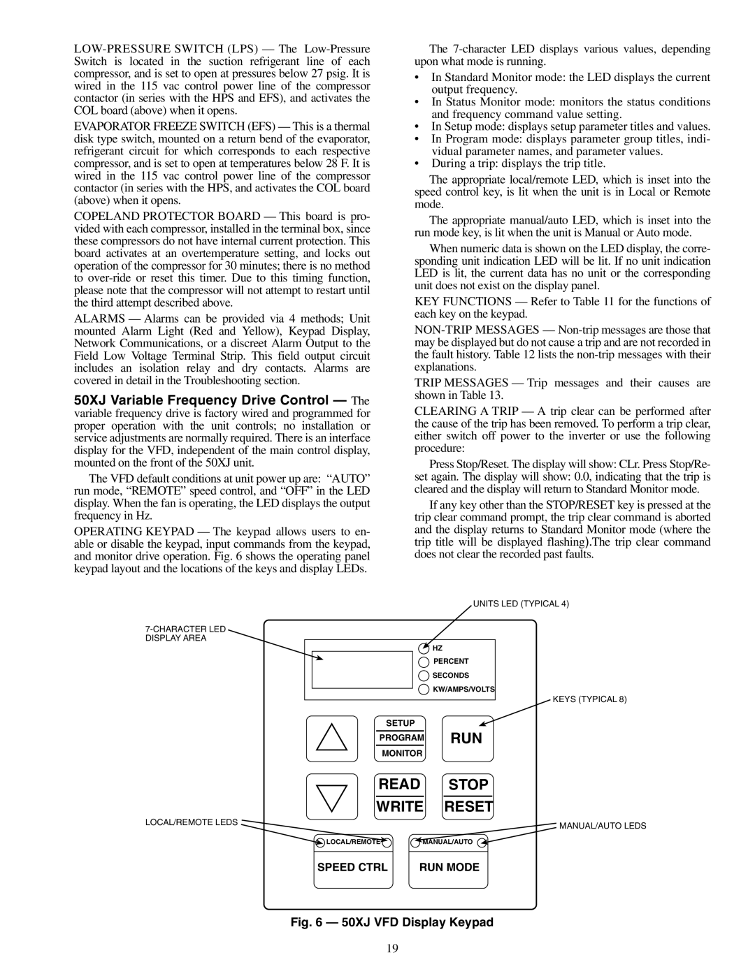
OPERATING KEYPAD — The keypad allows users to en- able or disable the keypad, input commands from the keypad, and monitor drive operation. Fig. 6 shows the operating panel keypad layout and the locations of the keys and display LEDs.

The 7-character LED displays various values, depending upon what mode is running.

In Standard Monitor mode: the LED displays the current output frequency.

In Status Monitor mode: monitors the status conditions and frequency command value setting.

In Setup mode: displays setup parameter titles and values.

In Program mode: displays parameter group titles, indi- vidual parameter names, and parameter values.

During a trip: displays the trip title.

The appropriate local/remote LED, which is inset into the speed control key, is lit when the unit is in Local or Remote mode.

The appropriate manual/auto LED, which is inset into the run mode key, is lit when the unit is Manual or Auto mode.

When numeric data is shown on the LED display, the corre- sponding unit indication LED will be lit. If no unit indication LED is lit, the current data has no unit or the corresponding unit does not exist on the display panel.

KEY FUNCTIONS — Refer to Table 11 for the functions of each key on the keypad.

NON-TRIP MESSAGES — Non-trip messages are those that may be displayed but do not cause a trip and are not recorded in the fault history. Table 12 lists the non-trip messages with their explanations.

TRIP MESSAGES — Trip messages and their causes are shown in Table 13.

CLEARING A TRIP — A trip clear can be performed after the cause of the trip has been removed. To perform a trip clear, either switch off power to the inverter or use the following procedure:

Press Stop/Reset. The display will show: CLr. Press Stop/Re- set again. The display will show: 0.0, indicating that the trip is cleared and the display will return to Standard Monitor mode.

If any key other than the STOP/RESET key is pressed at the trip clear command prompt, the trip clear command is aborted and the display returns to Standard Monitor mode (where the trip title will be displayed flashing).The trip clear command does not clear the recorded past faults.


UNITS LED (TYPICAL 4)

7-CHARACTER LED


DISPLAY AREA


HZ


PERCENT


SECONDS


KW/AMPS/VOLTS


KEYS (TYPICAL 8)

SETUP


PROGRAM

RUN

MONITOR


READ

STOP

WRITE

RESET

LOCAL/REMOTE LEDS


MANUAL/AUTO LEDS


LOCAL/REMOTE

MANUAL/AUTO

SPEED CTRL

RUN MODE

Fig. 6 — 50XJ VFD Display Keypad

19

Page 19
Image 19
Carrier 50XJ064-104 specifications Run

50XJ064-104 specifications

The Carrier 50XJ064-104 is a high-efficiency rooftop air conditioning system designed to deliver exceptional cooling and heating capabilities for diverse commercial applications. One of the standout features of this model is its robust cooling capacity of 64,000 BTUs, making it suitable for mid to large-sized spaces. The 50XJ064-104 is engineered using advanced technologies to ensure energy efficiency and reliable performance, contributing to reduced operational costs and environmental sustainability.

One of the primary technologies employed in the Carrier 50XJ064-104 is the high-efficiency scroll compressor. This component plays a pivotal role in optimizing energy usage while delivering consistent cooling output. The system also incorporates an economizer that allows for enhanced energy savings by utilizing outdoor air for cooling when conditions are favorable. This not only decreases reliance on the compressor but also improves indoor air quality.

The microprocessor-based controls in the 50XJ064-104 provide precise temperature regulation, ensuring optimal comfort levels in various applications. These controls allow for easy programming and can be integrated into building management systems for centralized oversight. Additionally, the unit features a built-in fault detection and diagnostic system that aids in identifying potential issues before they escalate, minimizing downtime and maintenance costs.

The Carrier 50XJ064-104 is designed with durability in mind. It features a weather-resistant cabinet, designed to withstand harsh outdoor conditions and prolong service life. The high-quality insulation within the unit not only enhances energy efficiency but also minimizes noise levels, making it an ideal choice for urban environments where sound control is critical.

Another important characteristic is its environmentally friendly R-410A refrigerant, which has a lower impact on ozone depletion compared to older refrigerants. This aligns with Carrier's commitment to creating sustainable HVAC solutions that comply with current environmental regulations.

Overall, the Carrier 50XJ064-104 stands out for its combination of efficiency, advanced technologies, and durable construction. Whether for commercial buildings, retail spaces, or industrial applications, this rooftop air conditioning unit is designed to provide reliable performance and comfort year-round.