GE EPM 6000 Multi-function Power Metering System Configuring the Connection Setting

Models: EPM 6000 EPM 6000 Multi-function Power Metering System

1 100
Download 100 pages 59.45 Kb
Page 65
Image 65

CHAPTER 4: USING THE METER

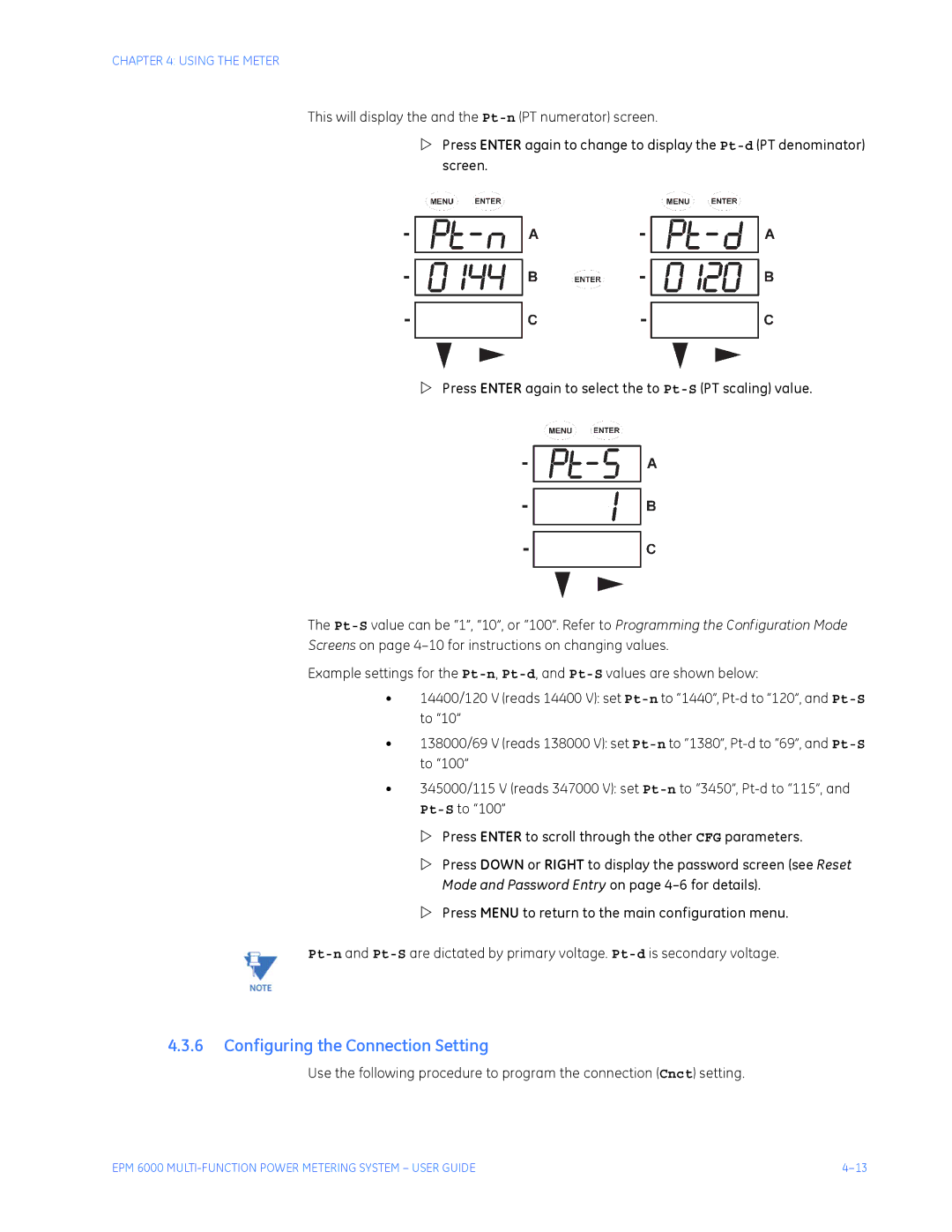
This will display the and the Pt-n(PT numerator) screen.

ZPress ENTER again to change to display the Pt-d(PT denominator) screen.

ZPress ENTER again to select the to Pt-S(PT scaling) value.

The Pt-Svalue can be “1”, “10”, or “100”. Refer to Programming the Configuration Mode

Screens on page 4–10 for instructions on changing values.

Example settings for the Pt-n, Pt-d, and Pt-Svalues are shown below:

14400/120 V (reads 14400 V): set Pt-nto “1440”, Pt-d to “120”, and Pt-Sto “10”

138000/69 V (reads 138000 V): set Pt-nto “1380”, Pt-d to “69”, and Pt-Sto “100”

345000/115 V (reads 347000 V): set Pt-nto “3450”, Pt-d to “115”, and Pt-Sto “100”

Z Press ENTER to scroll through the other CFG parameters.

Z Press DOWN or RIGHT to display the password screen (see Reset Mode and Password Entry on page 4–6 for details).

Z Press MENU to return to the main configuration menu.

Pt-nand Pt-Sare dictated by primary voltage. Pt-dis secondary voltage.

4.3.6Configuring the Connection Setting

Use the following procedure to program the connection (Cnct) setting.

EPM 6000 MULTI-FUNCTION POWER METERING SYSTEM – USER GUIDE

4–13

Page 65
Image 65
GE EPM 6000 Multi-function Power Metering System instruction manual Configuring the Connection Setting